Z15GW-B Omron, Z15GW-B Datasheet - Page 18
Z15GW-B
Manufacturer Part Number
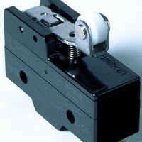
Z15GW-B
Description
Basic / Snap Action / Limit Switches HINGE LEVER SPDT
Manufacturer
Omron
Type
Snap Actionr
Series
Zr
Datasheet
1.Z-15HW24-B.pdf
(25 pages)
Specifications of Z15GW-B
Contact Form
SPDT
Contact Rating
15 Amps at 250 Volts
Actuator
Lever, Hinge
Operating Force
500 g
Termination Style
Screw
Lead Free Status / RoHS Status
Lead free / RoHS Compliant


Flexible Rod (Coil Spring)
Z-15GNJ55-B
Flexible Rod (Steel Wire)
Z-15HNJS55-B
Note: Unless otherwise specified, a tolerance of ±0.4 mm applies to all dimensions.
(111.3)
(130.1)
100
(13.6)
(13.8)
43.4
16.3
16.3
38
± 0.4
4.2
4.2
(22)
+0.075
+0.075
-0.025
-0.025
PT
PT
4.36
4.36
25.4
25.4
49.2
49.2
23.3
23.3
+0.1
+0.1
-0.05
-0.05
30 Operating range *2
30 Operating range *2
± 0.1
± 0.1
Four, M3 set screws
with hexagonal holes
± 0.25
± 0.25
Rubber cap
Rubber cap
dia.
dia.
11.9
11.9
4.2
4.2
+0.075
+0.075
-0.025
-0.025
dia. hole
dia. hole
1-dia. stainless
steel wire *3
Nylon rod
12 dia.
12 dia.
9.2
9.2
6.1 dia.
3.2 dia.
17.45
17.45
*1
*1
± 0.2
± 0.2
*1. Operation is possible in any direction other than the
*2. Use only the area within the top 30 mm of the rod as
*1. Operation is possible in any direction other than the axial
*2. Use only the area within the top 30 mm of the rod as the
*3. The steel wire can be replaced if damaged.
axial direction (indicated by the arrow
the operating part. (Do not use the area that falls within
80 mm from the mounting hole as the operating part.
Using this area may cause damage to the nylon rod.
direction (indicated by the arrow
operating part. (Do not use the area that falls within 100
mm from the mounting hole as the operating part.
Using this area may cause damage to the steel wire.)
(Model: Lever for HNJS55)
OF max.
PT max.
TT max.
OF max.
PT max.
).
).
(20 mm)
(25 mm)
0.49 N
40 mm
0.15 N
18
Z
Related parts for Z15GW-B
Image
Part Number
Description
Manufacturer
Datasheet
Request
R


Part Number:
Description:
G6S-2GLow Signal Relay
Manufacturer:
Omron Corporation
Datasheet:
Part Number:
Description:
Compact, Low-cost, SSR Switching 5 to 20 A
Manufacturer:
Omron Corporation
Datasheet:
Part Number:
Description:
Manufacturer:
Omron Corporation
Datasheet:
Part Number:
Description:
Manufacturer:
Omron Corporation
Datasheet:
Part Number:
Description:
Manufacturer:
Omron Corporation
Datasheet:
Part Number:
Description:
Manufacturer:
Omron Corporation
Datasheet:
Part Number:
Description:
Manufacturer:
Omron Corporation
Datasheet:
Part Number:
Description:
Manufacturer:
Omron Corporation
Datasheet: