B3F-6052 Omron, B3F-6052 Datasheet - Page 5
B3F-6052
Manufacturer Part Number
B3F-6052
Description
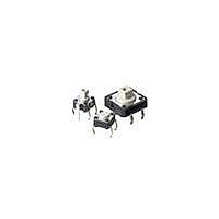
Tactile & Jog Switches Key Sw. In Ammo Pack
Manufacturer
Omron
Series
B3Fr
Type
Miniaturer
Datasheet
1.B3F-1052.pdf
(12 pages)
Specifications of B3F-6052
Operating Force
150 g
Actuator
Raised
Contact Form
SPST - NO
Termination Style
Solder Pin
Features
Miniature Space Saving Switch
Operating Temperature Range
- 25 C to + 70 C
Pole Throw Configuration
SPST
Switch Function Configuration
N.O.
Actuator Style
Projected Plunger
Actuator Color
Yellow
Actuator Length (mm)
3mm
Current Rating (max)
0.05A
Illumination Type
Not Required
Voltage Rating (vdc)
24V
Ground Terminal
No
Contact Plating
Gold
Product Length (mm)
6mm
Product Depth (mm)
6.2mm
Product Height (mm)
7.3mm
Operating Temp Range
-25C to 70C
Body Orientation
Straight
Mounting Style
Through Hole
Terminal Type
PC Pins
Contact Configuration
SPST-NO
Contact Current Max
50mA
Switch Terminals
Through Hole
Mounting Type
PCB
Operating Force Max
150gf
Circuitry
SPST-NO
Switch Operation
Off-(On)
Lead Free Status / RoHS Status
Lead free / RoHS Compliant
Other names
B3F6052BYOMZ BY OMZ


Dimensions
Note: 1. Unless otherwise specified, all units are in millimeters and a tolerance of ± 0.4 mm applies to all dimensions.
■ 6 x 6 mm Models
Standard, Flat Plunger Type
(without Ground Terminal)
Standard, Flat Plunger Type
(with Ground Terminal, Pitch: 7.5 mm)
B3F-1000, B3F-1002, B3F-1005, B3F-1020*, B3F-1022*,
B3F-1025*, B3F-1002-G, B3F-1022-G*
B3F-1110
Standard, Flat Plunger Type
(with Ground Terminal, Pitch: 6.5 mm)
B3F-1100, B3F-1102, B3F-1105, B3F-1120*, B3F-1122*,
B3F-1125*, B3F-1102-G, B3F-1122-G*
4.3
4.3
6
6
* The height of B3F-1020, B3F-1022, B3F-1025, and B3F-1026 is 5±0.2 mm.
3.5
3.5
±0.2
±0.2
±0.2
±0.2
(See note.)
*The height of B3F-1120, B3F-1122, and
(See note.)
6
5
2. Terminal numbers are not indicated on this switch. With the switch turned over so that the logo mark “OMRON” is visible on the upper
3.5
±0.2
±0.2
B3F-1125 is 5±0.2 mm.
part of the rear side of the switch base, the terminal on the right of the logo mark is numbered “1” and that on the bottom right is “3.”
Accordingly, two terminals on the left side are numbered “2” and “4” respectively.
6.5
7.7
6.5
7.7
6
6
0.7
±0.2
±0.2
±0.5
±0.5
±0.5
±0.5
1.5
7.5
6
9
0.7
±0.2
±0.5
±0.5
0.3
4.5
0.3
4.5
3.4
1.5
3.4
±0.2
±0.2
0.3
4.5
0.3
3.4
±0.2
0.7
0.7
dia.
3.5
0.3
dia.
3.5
0.7
0.7
0.7
dia.
3.5
Terminal Arrangement/Internal
Connections (Top View)
Terminal Arrangement
/Internal Connections (Top View)
0.7
4.1
PCB Mounting (Top View)
(Single-sided PCB, t=1.6)
±0.1
PCB Mounting (Top View)
(Single-sided PCB, t=1.6)
4
2
4
2
4.1
6.5
6.5
±0.1
5
±0.1
PCB Mounting (Top View)
(Single-sided PCB, t=1.6)
±0.1
3
1
Four, 1
3
1
1
±0.05
4.5
Five, 1
7.5
4.5
±0.1
±0.1
dia.
±0.1
±0.1
±0.05
dia.
1.2
dia.
±0.05
Four,
4.5
dia.
±0.1
7.3
7.3
Terminal Arrangement/Internal
Connections (Top View)
±0.2
±0.2
Standard, Projected Plunger Type
(without Ground Terminal)
B3F-1050, B3F-1052, B3F-1055
Standard, Projected Plunger Type
(with Ground Terminal)
B3F-1150, B3F-1152, B3F-1155
4.3
4.3
6
6
3.5
3.5
±0.2
±0.2
±0.2
±0.2
4
2
2.4 2.4
2.4 2.4
6.5
7.7
6.5
7.7
6
6
0.7
±0.2
±0.2
5
±0.5
±0.5
±0.5
±0.5
±0.1
±0.1
1.5
0.3
0.3
4.5
1.8
4.5
1.8
3
1
3.4
3.4
±0.2
±0.1
±0.2
±0.1
0.3
Tactile Switch
0.7
0.7
3.5 dia.
3.5 dia.
0.7
0.7
Terminal Arrangement/Internal
Connections (Top View)
4.1
PCB Mounting (Top View)
(Single-sided PCB, t=1.6)
±0.1
Terminal Arrangement/
Internal Connections
(Top View)
PCB Mounting (Top View)
(Single-sided PCB, t=1.6)
4
2
B3F
4
2
6.5
6.5
±0.1
5
±0.1
Five, 1
Four,
1
3
1
±0.05
3
1
4.5
±0.05
225
±0.2
dia.
4.5
dia.
±0.1
Related parts for B3F-6052
Image
Part Number
Description
Manufacturer
Datasheet
Request
R

Part Number:
Description:
Pushbutton Switch,STRAIGHT,SPST,OFF-(ON),PC TAIL W/RETNN Terminal,PCB Hole Count:6
Manufacturer:
Omron
Datasheet:

Part Number:
Description:
Pushbutton Switch,STRAIGHT,SPST,OFF-(ON),PC TAIL W/RETNN Terminal,PCB Hole Count:6
Manufacturer:
Omron
Datasheet:

Part Number:
Description:
Pushbutton Switch,STRAIGHT,SPST,OFF-(ON),PC TAIL W/RETNN Terminal,PCB Hole Count:6
Manufacturer:
Omron
Datasheet:

Part Number:
Description:
Pushbutton Switch,STRAIGHT,SPST,OFF-(ON),PC TAIL W/RETNN Terminal,PCB Hole Count:6
Manufacturer:
Omron
Datasheet:

Part Number:
Description:
Pushbutton Switch,STRAIGHT,SPST,OFF-(ON),PC TAIL W/RETNN Terminal,PCB Hole Count:6
Manufacturer:
Omron
Datasheet:

Part Number:
Description:
Pushbutton Switch,STRAIGHT,SPST,OFF-(ON),PC TAIL W/RETNN Terminal,PCB Hole Count:5
Manufacturer:
Omron
Datasheet:

Part Number:
Description:
Pushbutton Switch,STRAIGHT,SPST,OFF-(ON),PC TAIL W/RETNN Terminal,PCB Hole Count:6
Manufacturer:
Omron
Datasheet:

Part Number:
Description:
SWITCH TACT 6MM MOM 100GF
Manufacturer:
Omron
Datasheet:

Part Number:
Description:
SWITCH TACT 6MM MOM 100GF
Manufacturer:
Omron
Datasheet:

Part Number:
Description:
SWITCH TACT 6MM 500GF H=4.3MM
Manufacturer:
Omron
Datasheet:

Part Number:
Description:
Pushbutton Switch,STRAIGHT,SPST,OFF-(ON),PC TAIL W/RETNN Terminal,PCB Hole Count:4
Manufacturer:
Omron
Datasheet:

Part Number:
Description:
Pushbutton Switch,STRAIGHT,SPST,OFF-(ON),PC TAIL W/RETNN Terminal,PCB Hole Count:4
Manufacturer:
Omron
Datasheet:

Part Number:
Description:
Pushbutton Switch,STRAIGHT,SPST,OFF-(ON),PC TAIL W/RETNN Terminal,PCB Hole Count:4
Manufacturer:
Omron
Datasheet:

Part Number:
Description:
Pushbutton Switch,STRAIGHT,SPST,OFF-(ON),PC TAIL W/RETNN Terminal,PCB Hole Count:4
Manufacturer:
Omron
Datasheet:

Part Number:
Description:
MECHANICAL KEYSWITCH
Manufacturer:
Omron
Datasheet: