E32-DC200 Omron, E32-DC200 Datasheet - Page 41
E32-DC200
Manufacturer Part Number
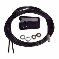
E32-DC200
Description
Fiber Optic Sensors M6 DIFF CABLE
Manufacturer
Omron
Type
Fiber Optic Cablesr
Specifications of E32-DC200
Cable Type
Fiber Optic Diffuse Top Beam
Features
Set-Mode blinking light source aids alignment
Sensing Method
Light
Sensing Distance
20.06 mm
Sensor Output
Analog
Sensor Housing
Barrel
Sensor Input
Fiber Optic
Sensing Range Max
400mm
Switch Terminals
Cable
Sensing Mode
Diffuse
Fiber Optic Sensor Type
General Purpose
Rohs Compliant
Yes
Lead Free Status / RoHS Status
Lead free / RoHS Compliant
Lead Free Status / RoHS Status
Lead free / RoHS Compliant, Lead free / RoHS Compliant
Available stocks
Company
Part Number
Manufacturer
Quantity
Price
Company:

Part Number:
E32-DC2004B4
Manufacturer:
OMRON
Quantity:
537
Company:
Part Number:
E32-DC200F4
Manufacturer:
FSC
Quantity:
12 900


Mounting hole dimensions (recommended)
<Screw-mounting Model>
Example: Head size of E32-TC200 is M4. Open the mounting holes with 4 to 4.5 dia.
<Cylindrical Model>
Example: Head size of E32-T22 is 2 dia.. Open the mounting holes with 2.2 to 2.4 dia.
Outer diameter of
fiber unit
F dimensions
Outer diameter of
fiber unit
F dimensions
Through-beam Fiber Units
Standard
Outer diameter of
fiber unit
F dimensions
E32-T24
E32-T24R
E32-T25Y
E32-T25YR
E32-T25Z
E32-T25ZR
7 7
2 2
Note: 1. Set of two symmetrical parts.
Note: 1. Set of two symmetrical parts.
7 7 4.5
4.5 1
Sensing
surface
1.25
2.5
R10
2 2
Stainless-steel tube
1 dia. max.
2.5
Sensing
surface
15
15
R10
Standard/Flexible Models
R10
2. Mounting screws (countersunk screw M2 × 8 4 pcs) included
2. Mounting screws (countersunk screw M2 × 8 4 pcs) included
3
3
12
12
5
5
12
12
(aluminum)
1.2
35
3
4
3.5 dia.
1 dia.
Sensing surface
+0.5
+0.5
0
0
M3
+0.2
Two, 2.2 dia. mounting holes with
two, 4.4 dia. countersinks on one side
Two, 2.2 dia. mounting holes with
two, 4.4 dia. countersinks on one side
(aluminum)
0
15
15
dia.
dia.
dia. 1.7
2 dia.
2 dia. (SUS304)
F
4.5
4
1.5 dia.
1.4 dia.
4 dia.
+0.5
0
12
M4
+0.2
+0.5
Through-beam models consist of two parts: an emitter and a receiver.
0
0
dia.
dia. 2.2
dia. 5.5
2,000
Heat-shrinkable tube
2,000
6
E39-F9: Included
2 dia.
5 dia.
E39-F9: Included
1 dia.
+0.5
0
M6
+0.2
+0.5
E39-F9: Included
0
0
2,000
dia.
dia. 3.2
dia. 6.5
1 dia.
1 dia.
14 dia.
(Unit:mm)
(Unit:mm)
3 dia.
6 dia.
M14
+0.2
+0.5
+1
0
0
0
dia.
dia.
E32-T15Y
E32-T15YR
E32-T15Z
E32-T15ZR
Minimum bending radius
(except E32-C11N, E32-C31N
8 8
Flexible
(E32-C11N, E32-C31N,
3 3
Flexible
Note: 1. Set of two symmetrical parts.
Note: 1. Set of two symmetrical parts.
and E32-CC200)
E32-CC200R)
Sensing
surface
8 8
5.5
Cutting free (Cutter provided)
2.5
3 3
5.5
R25
2.5
R25
2. Mounting screws (countersunk screw M2 × 8 4 pcs) included
1.5
2. Mounting screws (countersunk screw M2 × 8 4 pcs) included
Type
R10
R25
R30
R35
R40
Break-resistant
4
4
Break-resistant
7.5
7.5
15
15
R4
15
15
(aluminum)
Sensing surface
Minimum bending radius
Two, 2.2 dia. mounting holes
with two, 4.4 dia. countersinks on both sides
(aluminum)
Two, 2.2 dia. mounting holes
with two, 4.4 dia. countersinks on both sides
Sensing
head
Minimum bending
A
unbendable
Fluororesin coating
Fluororesin coating
radius
B
10
25
30
35
40
A
1
4
4
2,000
2,000
unbendable
R@
R@
Standard
10
10
10
10
10
10
B
2.2 dia.
0
0
Standard
2.2 dia.
(Unit:mm)
41
Related parts for E32-DC200
Image
Part Number
Description
Manufacturer
Datasheet
Request
R

Part Number:
Description:
Fiber Optic Sensors 1.5mm DIA FLEXIBLE D IFFUSE FO
Manufacturer:
Omron
Datasheet:
Part Number:
Description:
Fiber Optic Sensors HIGHFLEX HIGHTEMP D IFFUSE R10
Manufacturer:
Omron
Datasheet:

Part Number:
Description:
Fiber Optic Sensors 10 METER CABLE
Manufacturer:
Omron
Datasheet:
Part Number:
Description:
Fiber Optic Sensors E32-CC200 WITH 10M Cable
Manufacturer:
Omron

Part Number:
Description:
Fiber Optic Sensors M3 THRU-BEAM CABLE
Manufacturer:
Omron
Datasheet:

Part Number:
Description:
Fiber Optic Sensors M3 DIFF CABLE
Manufacturer:
Omron
Datasheet:

Part Number:
Description:
Fiber Optic Sensors SIDE VIEW CABLE
Manufacturer:
Omron
Datasheet:

Part Number:
Description:
Fiber Optic Sensors COAX DIFF CABLE
Manufacturer:
Omron
Datasheet:

Part Number:
Description:
Fiber Optic Sensors M4 THRU-BEAM CABLE
Manufacturer:
Omron
Datasheet:

Part Number:
Description:
G6S-2GLow Signal Relay
Manufacturer:
Omron Corporation
Datasheet:
Part Number:
Description:
Compact, Low-cost, SSR Switching 5 to 20 A
Manufacturer:
Omron Corporation
Datasheet:
Part Number:
Description:
Manufacturer:
Omron Corporation
Datasheet: