E2E-X3D1-M1GJ Omron, E2E-X3D1-M1GJ Datasheet - Page 21
E2E-X3D1-M1GJ
Manufacturer Part Number
E2E-X3D1-M1GJ
Description
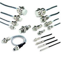
Proximity Sensors M8 SHLD 2WIRE INLINE CONN.
Manufacturer
Omron
Type
Inductive Proximity Sensorr
Series
E2Er
Datasheet
1.E2E-X18ME1.pdf
(37 pages)
Specifications of E2E-X3D1-M1GJ
Maximum Operating Temperature
+ 70 C
Supply Voltage
30 V
Output Voltage
3 V
Operating Supply Voltage
12 V to 24 V
Mounting Style
Panel
Minimum Operating Temperature
- 25 C
Maximum Output Current
100 mA
Features
High visibility indicator
Sensing Distance
3 mm
Lead Free Status / RoHS Status
Lead free / RoHS Compliant


I/O Circuit Diagrams
E2E-X@D@ DC 2-Wire Models
diagnostic
diagnostic
diagnostic
Operation
With self-
Without
Without
output:
output:
output:
mode
self-
self-
NO
NC
NO
E2E-X@D1-N
E2E-X@D1-M1G(J)
E2E-X@D1-(M1TGJ)-U
E2E-X@D1-M3G
E2E-X@D1-M1J-T
E2E-X@D2-N
E2E-X@D2-M1G
E2E-X@D2-(M1TGJ)-U
E2E-X@D2-M3G
E2E-X@D1S
E2E-X@D1S-M1
Model
* The diagnostic output is ON when there is a coil
burnout or the sensing object is located in the
unstable sensing area for 0.3 s or longer.
Non-sensing
Non-sensing
Sensing
object
Sensing
object
(%)
Sensing
object
(%)
(%)
Non-sensing
area
area
area
Rated
sensing
distance
Rated
sensing
distance
Rated
sensing
distance
Unstable
sensing
area
Unstable
sensing
area
100
100
100
Timing Chart
80
Sensing area
80
Set position
Set position
Stable sensing area
Stable sensing area
0
0
ON
OFF
ON
OFF
0
ON
OFF
ON
OFF
ON
OFF
ON
OFF
ON
OFF
ON
OFF
ON
OFF
Proximity Sensor
Proximity Sensor
Proximity Sensor
Operation
indicator (red)
Control output
Setting indicator
(green)
Operation
indicator (red)
Control output
Diagnostic output*
Setting indicator
(green)
Operation
indicator (red)
Control output
Polarity: Yes
Polarity: None
Note 1. The load can be connected to either the +V or
Note: The load can be connected to either the +V
Note: The load can be connected to either the
Note: Connect both the loads to the +V side of
Prox-
imity
Sensor
main
circuit
Prox-
imity
Sensor
main
circuit
Prox-
imity
Sensor
main
circuit
2. The E2E-X@D1-M1J-T has no polarity.
Prox-
imity
Sensor
main
circuit
or 0 V side.
+V or 0 V side.
the control output and diagnostic output.
0 V side.
Therefore, terminals 3 and 4 have no polarity.
Output circuit
Brown (4)
Blue (3)
Orange (2)
(diagnostic
output)
Brown
Blue
1
4
4
Brown
3
2
Blue
1
Load
Load
Load
Load
Load
0 V
+V
(0 V)
(+V)
0 V
+V
0 V
+V
+V
+V
0
E2E
21
Related parts for E2E-X3D1-M1GJ
Image
Part Number
Description
Manufacturer
Datasheet
Request
R


Part Number:
Description:
Proximity Sensors E2E-X3D1 w/0.5M Cbl M12T Cn.
Manufacturer:
Omron
Part Number:
Description:
Proximity Sensors E2E-X3D1 W/ M12 PIGT AIL CONN.
Manufacturer:
Omron
Part Number:
Description:
PROX, PTFE
Manufacturer:
Omron
Datasheet:
Part Number:
Description:
Proximity Sensors CENELEL METAL CONNE CONNECTOR
Manufacturer:
Omron
Datasheet:
Part Number:
Description:
Proximity Sensors TEFLON PROX.
Manufacturer:
Omron
Datasheet:
Part Number:
Description:
Proximity Sensors INDUCTIVE M12 3mm
Manufacturer:
Omron
Datasheet:
Part Number:
Description:
Proximity Sensors Prox M12 3Mm No 5M
Manufacturer:
Omron
Datasheet:
Part Number:
Description:
Proximity Sensors PROX PLUG IN
Manufacturer:
Omron
Datasheet:

Part Number:
Description:
PROXIMITY SENSOR
Manufacturer:
Omron
Datasheet: