E2EC-CR8D1 Omron, E2EC-CR8D1 Datasheet - Page 8
E2EC-CR8D1
Manufacturer Part Number
E2EC-CR8D1
Description
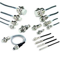
Proximity Sensors PROX 3mm In-line Amp DC2W-NO
Manufacturer
Omron
Type
Miniature Inductive Proximity Sensorr
Series
E2E2Cr
Specifications of E2EC-CR8D1
Maximum Operating Temperature
+ 70 C
Supply Voltage
24 V
Operating Supply Voltage
10 V to 30 V
Minimum Operating Temperature
- 25 C
Maximum Output Current
100 mA
Barrel Size
3 mm diameter
Features
Side-by-side mounting of cable amplifier units possible
Sensing Distance
3 mm
Sensor Input
Inductive
Sensing Range
0.8mm
Supply Voltage Range Dc
10V To 30V
Mounting Type
Panel
Switch Terminals
Cable
Load Current Rms Max
100mA
Sensing Face Diameter
3mm
Supply Voltage Min
10VDC
Sensor Type
Inductive
Sensing Object
Metallic
Response Frequency
1.5kHz
Material - Body
Brass
Shielding
Shielded
Voltage - Supply
10 V ~ 30 V
Output Type
NPN-NO
Terminal Type
2-Wire
Package / Case
Cylinder with Amplifier
Rohs Compliant
Yes
Lead Free Status / RoHS Status
Lead free / RoHS Compliant
Lead Free Status / RoHS Status
Lead free / RoHS Compliant, Lead free / RoHS Compliant
Available stocks
Company
Part Number
Manufacturer
Quantity
Price
Company:

Part Number:
E2EC-CR8D1
Manufacturer:
QT
Quantity:
8 570


E2EC
Precautions
J MOUNTING
Refer to the following table for the torque and tightening ranges
applied to mount unthreaded E2EC-C models.
Permissible Tightening Range and Torque
The tightening torque applied to the E2EC-X4D (i.e., models with
column screws) must be 120 kgf S cm (12 N S m) max.
8
Model
E2EC-CR8D
E2EC-C1R5D
E2EC-C3D
E2EC-CR5j1
E2EC-C2R5j1
Tightening
range A
6 to 10 mm
(0.24 to 0.39 in)
8 to 16 mm
(0.31 to 0.62 in)
8 to 16 mm
(0.31 to 0.62 in)
6 to 10 mm
(0.24 to 0.39 in)
8 to 16 mm
(0.31 to 0.62 in)
M3 set screw hole
Set-screw tightening
torque
5 kgf S cm {0.49 N S m}
(0.36 ft S lbf)
5 kgf S cm {0.49 N S m}
(0.36 ft S lbf)
10 kgf S cm {0.98 N S m}
(0.72 ft S lbf)
4 kgf S cm {0.39 N S m}
(0.29 ft S lbf)
(
)
J EFFECTS OF SURROUNDING METAL
When mounting the E2EC within a metal panel, ensure that the
clearances given in the following table are maintained.
Mounting Conditions
J MUTUAL INTERFERENCE
When mounting more than one E2EC face to face or side by
side, ensure that the minimum distances given in the following
table are maintained.
Note: Figures in brackets are for Sensors operating at different
Item
ℓ
d
D
m
n
Item
A
B
frequencies.
E2EC-
CR8D
8 [4]
0.32
(0.16)
6 [3]
0.24
(0.12)
E2EC-
CR8D
0
3
(0.12)
0
2.4
(0.94)
6
(0.24)
E2EC-
C1R5D
15 [8]
0.59
(0.32)
10.8
[5.4]
0.43
(0.21)
E2EC-
C1R5
D
0
5.4
(0.25)
0
4.5
(0.17)
10.8
(0.43)
E2EC-
C3D
30 [15]
1.18
(0.59)
16 [8]
0.63
(0.32)
E2EC-
C3D
0
8
(0.32)
0
9
(0.35)
16
(0.63)
E2EC-
X4D
40 [20]
1.57
(0.78)
24 [12]
0.94
(0.47)
d dia.
E2EC-
X4D
0
12
(0.47)
0
12
(0.47)
24
(0.94)
E2EC-
CR5j1
20 [10]
0.78
(0.39)
15 [3]
0.59
(0.12)
E2EC-
CR5j
1
0
3
(0.12)
0
1.5
(0.06)
5
(0.20)
E2EC-C
2R5j1
40 [20]
1.57
(0.78)
25 [15]
0.98
(0.59)
E2EC
E2EC-
C2R5
j1
0
8
(0.32)
0
10
(0.39)
21
(0.83)
Related parts for E2EC-CR8D1
Image
Part Number
Description
Manufacturer
Datasheet
Request
R

Part Number:
Description:
Proximity Sensors 3mm .5mm SENS NPN
Manufacturer:
Omron
Datasheet:
Part Number:
Description:
Proximity Sensors INDUCTIVE N.O. PNP
Manufacturer:
Omron
Datasheet:

Part Number:
Description:
Inductive Proximity Sensor
Manufacturer:
Omron
Datasheet:
Part Number:
Description:
Inductive Proximity Sensor
Manufacturer:
Omron
Datasheet:
Part Number:
Description:
PROX 3mm In-line Amp DC2W-NC
Manufacturer:
Omron
Datasheet:
Part Number:
Description:
PROX 8mm In-line Amp PNP-NO
Manufacturer:
Omron
Datasheet:
Part Number:
Description:
Proximity Sensors PROX 5.4mm In-line A mp DC2W-NC
Manufacturer:
Omron
Datasheet:
Part Number:
Description:
Proximity Sensors PROX 8mm In-line Amp DC2W-NC
Manufacturer:
Omron
Datasheet:
Part Number:
Description:
Proximity Sensors E2EC-C1R51 W/ M12 PI GTAIL CONN
Manufacturer:
Omron
Part Number:
Description:
Proximity Sensors PROX E2EC-C2R5C1 W/ 5M CABLE
Manufacturer:
Omron
Datasheet:

Part Number:
Description:
PROXIMITY SENSOR
Manufacturer:
Omron
Datasheet:
