E2K-X15MF1 Omron, E2K-X15MF1 Datasheet - Page 2
E2K-X15MF1
Manufacturer Part Number
E2K-X15MF1
Description
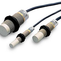
Proximity Sensors Cap M30 15 mm PNP-NO
Manufacturer
Omron
Type
Proximity Sensorr
Series
E2K-Xr
Specifications of E2K-X15MF1
Maximum Operating Temperature
+ 55 C
Supply Voltage
12 VDC to 24 VDC
Supply Current
15 mA
Output Voltage
1 V
Operating Supply Voltage
10 VDC to 30 VDC
Mounting Style
Panel
Minimum Operating Temperature
- 25 C
Current Rating
200 mA
Features
Permits non-contact detection of metallic and non-metallic objects
Voltage Rating
24 VDC
Sensing Distance
15 mm
Supply Voltage Range Dc
10V To 30V
Sensor Housing
Cylindrical
Sensor Input
Capacitive
Sensing Range Max
15mm
Switch Terminals
Cable
Sensor Output
PNP-NO
Sensor Type
Capacitive
Sensing Object
Metallic and Non-Metallic
Response Frequency
100Hz
Material - Body
ABS Plastic
Shielding
Unshielded
Voltage - Supply
10 V ~ 30 V
Output Type
PNP-NO
Terminal Type
3-Wire
Package / Case
Cylinder, Threaded - M30
Lead Free Status / RoHS Status
Lead free / RoHS Compliant
Lead Free Status / RoHS Status
Lead free / RoHS Compliant, Lead free / RoHS Compliant


Ratings and Specifications
*1. The above values are sensing distances for the standard sensing object. Refer to Engineering Data on page 3 for other materials.
*2. E Models (DC switching models): A full-wave rectification power supply of 24 VDC ±20% (average value) can be used.
Item
Sensing distance
Set distance *1
Differential travel
Detectable object
Standard sensing object
Response frequency
Power supply voltage*2
(operating voltage range)
Current consumption
Leakage current
Control
output
Indicators
Operation mode
(with sensing object
approaching)
Protection circuits
Ambient temperature
range
Ambient humidity range
Temperature influence
Voltage influence
Insulation resistance
Dielectric strength
Vibration resistance
Shock resistance
Degree of protection
Connection method
Weight (packed state)
Materi-
als
Accessories
Load current
Residual voltage E Models: 1 V max. (Load current: 200 mA, Cable length: 2 m), Y Models: Refer to Engineering Data on page 4.
Case
Sensing surface
Clamping nuts
Model
4mm ±10%
0 to 2.8 mm
4% to 20% of sensing distance
Conductors and dielectrics
Grounded metal plate: 50 × 50 × 1 mm
E Models: 100 Hz, Y Models: 10 Hz
E Models: 12 to 24 VDC (10 to 30 VDC)
Y Models: 100 to 220 VAC (90 to 250 VAC)
E Models: 15 mA max.
Y Models: 2.2 mA max. (Refer to page 4.)
E Models: 200 mA max.*2, Y Models: 10 to 200 mA
E Models: Detection indicator (red), Y Models: Operation indicator (red)
E1/Y1 Models: NO
E2/Y2 Models: NC
E Models: Reverse polarity protection, Surge suppressor, Y Models: Surge suppressor
Operating/Storage: −25 to 70°C (with no icing or condensation)
Operating/Storage: 35% to 95% (with no condensation)
±20% max. of sensing distance at 23°C in the operating temperature range
E Models: ±2% max. of sensing distance at rated voltage at rated voltage ±20%
Y Models: ±2% max. of sensing distance at rated voltage at rated voltage ±10%
50 MΩ min. (at 500 VDC) between current-carrying parts and case
E Models: 1,000 VAC, 50/60 Hz for 1 min between current-carrying parts and case
Y Models: 2,000 VAC, 50/60 Hz for 1 min between current-carrying parts and case
Destruction: 10 to 55 Hz, 1.5-mm double amplitude for 2 hours each in X, Y, and Z directions
Destruction: 500 m/s
IP66 (IEC), in-house standards: oil-resistant
Pre-wired Models (Standard cable length: 2 m)
Approx. 65 g
Heat-resistant ABS
Polyacetal
Tightening tool, Instruction Manual
E2K-X4ME@,
E2K-X4MY@
2
Refer to the timing charts under I/O Circuit Diagrams on page 4 for details.
3 times each in X, Y, and Z directions
8 mm ±10%
0 to 5.6 mm
Approx. 145 g
Instruction manual
E2K-X8ME@,
E2K-X8MY@
15 mm ±10%
0 to 10 mm
Operating/Storage: −10 to 55°C
(with no icing or condensation)
Approx. 205 g
E2K-X15ME@,
E2K-X15MY@
E2K-X
2
Related parts for E2K-X15MF1
Image
Part Number
Description
Manufacturer
Datasheet
Request
R

Part Number:
Description:
Proximity Sensors E2K-X8MY1 W/ 5 METER CABLE
Manufacturer:
Omron
Datasheet:

Part Number:
Description:
Proximity Sensors E2K-C25MY1 W/ 5 MET ER CABLE
Manufacturer:
Omron
Datasheet:
Part Number:
Description:
Proximity Sensors E2K-C25MY1 W/ 10 MET ER CABLE
Manufacturer:
Omron
Datasheet:
Part Number:
Description:
Proximity Sensors E2K C25ME1 W/ 5 METE R CABLE
Manufacturer:
Omron
Datasheet:
Part Number:
Description:
Proximity Sensors E2K-X8ME1 W/ 10 METE R CABLE
Manufacturer:
Omron
Datasheet:
Part Number:
Description:
Proximity Sensors E2K-C25MY2 W/ 5 METE R CABLE
Manufacturer:
Omron
Datasheet:
Part Number:
Description:
Proximity Sensors E2K-C25ME2 W/ 5 METE R CABLE
Manufacturer:
Omron
Datasheet:
Part Number:
Description:
Proximity Sensors E2K-X4ME1 W/ 5 METER CABLE
Manufacturer:
Omron
Datasheet:

Part Number:
Description:
Proximity Sensors E2K-F10MC2 W/ 5 MET ER CABLE
Manufacturer:
Omron
Datasheet:
Part Number:
Description:
Proximity Sensors E2K-F10MC1 W/ 5 METE R CABLE
Manufacturer:
Omron
Datasheet:
Part Number:
Description:
CAP PROX M12, 4mm PNP-NC
Manufacturer:
Omron
Datasheet:

Part Number:
Description:
G6S-2GLow Signal Relay
Manufacturer:
Omron Corporation
Datasheet:
Part Number:
Description:
Compact, Low-cost, SSR Switching 5 to 20 A
Manufacturer:
Omron Corporation
Datasheet:
Part Number:
Description:
Manufacturer:
Omron Corporation
Datasheet: