UCE-3.3/15-D48N-C Murata Power Solutions Inc, UCE-3.3/15-D48N-C Datasheet - Page 5
UCE-3.3/15-D48N-C
Manufacturer Part Number
UCE-3.3/15-D48N-C
Description
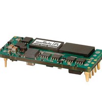
DC/DC Converters & Regulators 48Vin 3.3Vout 15A 49.5W Neg polarity
Manufacturer
Murata Power Solutions Inc
Specifications of UCE-3.3/15-D48N-C
Output Power
50 W
Input Voltage Range
36 V to 75 V
Input Voltage (nominal)
48 V
Number Of Outputs
1
Output Voltage (channel 1)
3.3 V
Output Current (channel 1)
15 A
Isolation Voltage
2.25 KV
Package / Case Size
Eighth Brick
Output Voltage
3.3 V
Product
Isolated
Dc / Dc Converter O/p Type
Eighth-Brick
No. Of Outputs
1
Input Voltage
36V To 75V
Power Rating
49.5W
Output Current
15A
Approval Bodies
CAN / CSA / EN / IEC / UL
Rohs Compliant
Yes
Lead Free Status / RoHS Status
Lead free / RoHS Compliant


SPECIFICATIONS, CONTINUED
(1) All models are tested and specifi ed with external 1||10 μF ceramic/tantalum output capaci-
tors and no external input capacitor. All capacitors are low ESR types. These capacitors are
necessary to accommodate our test equipment and may not be required to achieve specifi ed
performance in your applications. All models are stable and regulate within spec under no-load
conditions.
General conditions for Specifi cations are +25 deg.C, V
Adequate airfl ow must be supplied for extended testing under power.
(2) Input Ripple Current is tested and specifi ed over a 5 Hz to 20 MHz bandwidth. Input fi ltering
is C
(3) Note that Maximum Power Derating curves indicate an average current at nominal input
voltage. At higher temperatures and/or lower airfl ow, the DC/DC converter will tolerate brief
full current outputs if the total RMS current over time does not exceed the Derating curve. All
Derating curves are presented at sea level altitude. Be aware of reduced power dissipation
with increasing density altitude.
(4) Mean Time Before Failure is calculated using the Telcordia (Belcore) SR-332 Method 1, Case
3, ground fi xed conditions, Tpcboard=+25 deg.C, full output load, natural air convection.
(5) The On/Off Control is normally controlled by a switch. But it may also be driven with exter-
nal logic or by applying appropriate external voltages which are referenced to Input Common.
The On/Off Control Input should use either an open collector or open drain transistor.
(6) Short circuit shutdown begins when the output voltage degrades approximately 2% from
the selected setting.
Murata Power Solutions recommends the specifi cations below when installing these converters. These specifi cations vary depending on the solder type.
Exceeding these specifi cations may cause damage to the product. Your production environment may differ; therefore please thoroughly review these guidelines
with your process engineers.
Wave Solder Operations for through-hole mounted products (THMT)
For Sn/Ag/Cu based solders:
Maximum Preheat Temperature
Maximum Pot Temperature
Maximum Solder Dwell Time
For Sn/Pb based solders:
Maximum Preheat Temperature
Maximum Pot Temperature
Maximum Solder Dwell Time
Outline dimensions
Pin material
Pin diameter
Pin fi nish
Weight
Electromagnetic interference (external fi lter required)
Safety
PERFORMANCE SPECIFICATION NOTES
PHYSICAL CHARACTERISTICS
SOLDERING GUIDELINES
IN
= 33 μF, 100V tantalum, C
UCE-1.5/20-D48
UCE-1.8/30-D48,
UCE-2.5/20-D48
UCE-5/10-D48
UCE-5/20-D48
UCE-12/4.2-D48
UCE-3.3/15-D48
UCE-3.3/30-D48, UCE-12/8.3-D48, UCE-12/10-D48
BUS
= 220 μF, 100V electrolytic, L
115ºC.
270ºC.
7 seconds
105ºC.
250ºC.
6 seconds
IN
= nominal, V
BUS
= 12 μH.
OUT
= nominal, full load.
www.murata-ps.com
See mechanical specs (below)
Copper alloy
0.04/0.062" (1.016/1.524mm)
Nickel underplate with gold overplate
0.67 ounces (19 grams)
0.71 ounces (20 grams)
1 ounce (28 grams)
0.81 ounces (23 grams)
Meets EN55022/CISPR22 (requires external fi lter)
Certifi ed to UL/cUL 60950-1, CSA-C22.2 No. 60950-1, IEC/EN 60950-1, 2nd Edition
(7) The outputs are not intended to sink appreciable reverse current. This may damage the
outputs.
(8) Output noise may be further reduced by adding an external fi lter. See I/O Filtering and Noise
Reduction.
(9) All models are fully operational and meet published specifi cations, including “cold start” at
–40ºC.
(10) Regulation specifi cations describe the deviation as the line input voltage or output load
current is varied from a nominal midpoint value to either extreme.
(11) Alternate pin length and/or other output voltages are available under special quantity order.
(12) Output overvoltage is non-latching. When the overvoltage fault is removed, the converter
will immediately recover.
(13) Do not exceed maximum power specifi cations when adjusting the output trim.
(14) At zero output current, the output may contain low frequency components which exceed
the ripple specifi cation. The output may be operated indefi nitely with no load.
(15) If reverse polarity is accidentally applied to the input, a body diode will become forward bi-
ased and will conduct considerable current. To ensure reverse input protection with full output
load, always connect an external input fuse in series with the +V
Isolated, High-Density, Eighth-Brick
Low Profi le DC/DC Converters
21 Feb 2011
email: sales@murata-ps.com
UCE Series
MDC_UCE.A30 Page 5 of 17
IN
input.
Related parts for UCE-3.3/15-D48N-C
Image
Part Number
Description
Manufacturer
Datasheet
Request
R

Part Number:
Description:
CONV DC/DC 49.5W 3.3V 15A
Manufacturer:
Murata Power Solutions Inc
Datasheet:

Part Number:
Description:
DC/DC Converters & Regulators 48Vin 3.3Vout 15A 49.5W W/Baseplate
Manufacturer:
Murata Power Solutions Inc
Datasheet:
Part Number:
Description:
DC/DC Converters & Regulators 48Vin 3.3Vout 15A 49.5W Pos polarity
Manufacturer:
Murata Power Solutions Inc
Datasheet:

Part Number:
Description:
CONV DC/DC 99W 3.3V 30A
Manufacturer:
Murata Power Solutions Inc
Datasheet:
Part Number:
Description:
DC/DC Converters & Regulators 48Vin 3.3Vout 30A 99W Neg polarity
Manufacturer:
Murata Power Solutions Inc
Datasheet:
Part Number:
Description:
DC/DC Converters & Regulators 48Vin 3.3Vout 30A 99W Pos polarity
Manufacturer:
Murata Power Solutions Inc
Datasheet:
Part Number:
Description:
DC/DC Converters & Regulators 48Vin 3.3Vout 30A 99W W/Baseplate
Manufacturer:
Murata Power Solutions Inc
Datasheet:

Part Number:
Description:
POWER OVER ETHERNET MODULE
Manufacturer:
Murata Power Solutions Inc
Datasheet:

Part Number:
Description:
POWER OVER ETHERNET MODULE
Manufacturer:
Murata Power Solutions Inc
Datasheet:

Part Number:
Description:
Transformers 5Vin 5Vout 200mA 4000Vdc 1:1.33 turn
Manufacturer:
Murata Power Solutions Inc
Datasheet:

Part Number:
Description:
POWER SUPPLY
Manufacturer:
Murata Power Solutions Inc
Datasheet:

Part Number:
Description:
DPM LED MINI 2VDC 3.5DIG LP RED
Manufacturer:
Murata Power Solutions Inc
Datasheet:

Part Number:
Description:
CONV DC/DC 1W 5VIN 5VOUT SIP SGL
Manufacturer:
Murata Power Solutions Inc
Datasheet:

Part Number:
Description:
CONV DC/DC 1W 5VIN 3.3V SIP SGL
Manufacturer:
Murata Power Solutions Inc
Datasheet: