NMR112C Murata Power Solutions Inc, NMR112C Datasheet

DC/DC Converters & Regulators DC/DC TH 1W 15-5V SIP SINGLE

NMR112C

Manufacturer Part Number
NMR112C
Description
DC/DC Converters & Regulators DC/DC TH 1W 15-5V SIP SINGLE
Manufacturer
Murata Power Solutions Inc
Series
NMRr
Datasheet

Specifications of NMR112C

Output Power
1 W
Input Voltage Range
13.5 V to 16.5 V
Input Voltage (nominal)
15 V
Number Of Outputs
1
Output Voltage (channel 1)
5 V
Output Current (channel 1)
+/- 67 mA
Isolation Voltage
1 KV
Package / Case Size
SIP
Output Type
DC/DC Converter
Output Voltage
5 V
Product
Isolated
Lead Free Status / RoHS Status
Lead free / RoHS Compliant
www.murata-ps.com
FEATURES
DESCRIPTION
The NMR series of industrial temperature range
DC/DC converters are the standard building blocks
for on-board distributed power systems. They are
ideally suited for providing single rail supplies on
primarily digital boards with the added benefi t of
galvanic isolation to reduce switching noise. Sur-
face mount technology and advanced packaging
materials produce rugged reliable performance
over an extended temperature range from -40ºC
to 85ºC.
www.murata-ps.com
RoHS compliant
1kVDC isolation
Effi ciency up to 80%
Wide temperature performance at full
1 watt load, –40°C to 85°C
Power density up to 0.90W/cm
UL 94V-0 package material
Footprint from 1.17cm
Industry standard pinout
5V, 12V, 15V & 24V input
5V, 12V & 15V output
No heatsink required
Internal SMD construction
Fully encapsulated with toroidal magnetics
Custom solutions available
No electrolytic or tantalum capacitors
www.murata-ps.com/rohs
For full details go to
 
2
3
1. Calculated using MIL-HDBK-217FN2 with nominal input voltage at full load.
2. See derating graph.
3. See ripple & noise characterisation method.
All specifi cations typical at T
SELECTION GUIDE
NMR100C
NMR101C
NMR102C
NMR106C
NMR107C
NMR108C
NMR112C
NMR113C
NMR114C
NMR118C
NMR119C
NMR120C
INPUT CHARACTERISTICS
Parameter
Voltage range
Refl ected ripple current
OUTPUT CHARACTERISTICS
Parameter
Rated Power
Voltage Set Point Accuracy
Line regulation
ISOLATION CHARACTERISTICS
Parameter
Isolation voltage
Resistance
ABSOLUTE MAXIMUM RATINGS
Lead temperature 1.5mm from case for 10 seconds
Internal power dissipation
Input voltage V
Input voltage V
Input voltage V
Input voltage V
Order
Code
Nominal
2
Voltage
Input
IN
IN
IN
IN
12
12
12
15
15
15
24
24
24
, NMR100C, NMR101C, NMR102C
, NMR106C, NMR107C, NMR108C
, NMR112C, NMR113C, NMR114C
, NMR118C, NMR119C, NMR120C
V
5
5
5
Output
Voltage
A
=25°C, nominal input voltage and rated output current unless otherwise specifi ed.
12
15
12
15
12
15
12
15
V
5
5
5
5
Conditions
Continuous operation, 5V input types
Continuous operation, 12V input types
Continuous operation, 15V input types
Continuous operation, 24V input types
5V & 12V input types
15V & 24V input types
Conditions
T
See tolerance envelope
High V
Conditions
Flash tested for 1 second
Viso=1000VDC
A
=-40°C to 85°C
Current
Output
200
200
200
200
mA
83
67
83
67
83
67
83
67
IN
to low V
Technical enquiries email: mk@murata-ps.com, tel: +44 (0)1908 615232
Rated Load
Current at
Isolated 1W Single Output DC/DC Converters
Input
IN
290
260
253
121
110
110
mA
93
85
84
60
53
52
12.5
6.90
6.50
12.5
6.90
6.50
6.80
2.80
2.50
Typ. Max. Typ. Max.
Regulation
8.1
3.3
2.8
Load
13.4
7.70
7.50
13.4
7.70
7.50
3.50
3.5
4.0
10
10
4
4.6
4.3
5.3
14
12
14
Ripple &
6
5
4
8
7
8
Noise
2010-07-08 KDC_NMR.D01 Page 1 of 5
300°C
550mW
7V
15V
18V
28V
1000
10
10
10
10
10
10
20
15
20
15
15
15
Min.
10.8
13.5
21.6
Min.
Min.
3
4.5
10
NMR Series
Effi ciency
69
77
79
69
76
76
69
77
78
70
78
80
%
Typ.
Typ.
Typ.
1.6
1.0
12
15
24
5
5
Capacitance
Isolation
Max.
Max.
Max.
13.2
16.5
26.4
122
5.5
1.0
1.2
pF
28
33
40
36
58
56
27
58
67
61
98
10
2
mA p-p
Units
Units
Units
MTTF
%/%
VDC
1847
1485
2110
1790
1560
1253
kHrs
981
667
869
613
784
566
W
V
1

Related parts for NMR112C

NMR112C Summary of contents

Page 1

... Internal power dissipation Input voltage V , NMR100C, NMR101C, NMR102C IN Input voltage V , NMR106C, NMR107C, NMR108C IN Input voltage V , NMR112C, NMR113C, NMR114C IN Input voltage V , NMR118C, NMR119C, NMR120C IN 1. Calculated using MIL-HDBK-217FN2 with nominal input voltage at full load. 2. See derating graph. 3. See ripple & noise characterisation method. ...

Page 2

GENERAL CHARACTERISTICS Parameter Conditions 5V input types 12V input types Switching frequency 15V input types 24V input types TEMPERATURE CHARACTERISTICS Parameter Conditions Specifi cation All output types Storage 5V output types Case Temperature above ambient All other output types Cooling ...

Page 3

... Resistive load to the maximum power rating of the DC/DC converter. Connections should be made via twisted wires Measured values are multiplied obtain the specifi ed values. Differential Mode Noise Test Schematic SUPPLY www.murata-ps.com Start-up time μs NMR112C 744 NMR113C 1908 NMR114C 6620 NMR118C ...

Page 4

... DC/DC converter. The SRF (Self Resonant Frequency) should be >20MHz. Inductor L, μH SMD NMR100C 10 82103C NMR101C 47 82473C NMR102C 47 82473C NMR106C 10 82103C NMR107C 47 82473C NMR108C 47 82473C NMR112C 10 82103C NMR113C 47 82473C NMR114C 47 82473C NMR118C 10 82103C NMR119C 47 82473C NMR120C 47 82473C www.murata-ps.com DC Power Source DC ...

Page 5

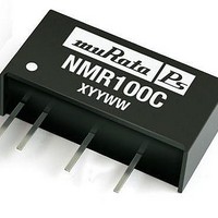
PACKAGE SPECIFICATIONS MECHANICAL DIMENSIONS 7 Pin SIP Package 0.77 (19.50) 0.236 (6.00) 0.394 (10.00) NMR100C XYYWWi 0.181 (4.60) 0.1 (2.54) 0.141 (3.60) 0.074±0.02 (1.88±0.50) 0.05 0.5 (12.70) (1.25) All dimensions in inches ±0.01 (mm ±0.25mm). All ...

Related keywords