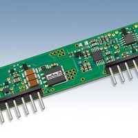
LSN2-T/30-D12G-C Murata Power Solutions Inc, LSN2-T/30-D12G-C Datasheet - Page 8

LSN2-T/30-D12G-C
Manufacturer Part Number
LSN2-T/30-D12G-C
Description
DC/DC Converters & Regulators 12Vin 0.8-5Vout 30A 150W Power Good Out
Manufacturer
Murata Power Solutions Inc
Series
LSN2r
Datasheet
1.LSN2-T30-D12-C.pdf
(16 pages)
Specifications of LSN2-T/30-D12G-C
Output Power
150 W
Input Voltage Range
6 V to 14 V
Input Voltage (nominal)
12 V
Number Of Outputs
1
Output Voltage (channel 1)
0.8 V to 5 V
Output Current (channel 1)
30 A
Package / Case Size
SIP
Output Type
Low Voltage Selectable
Output Voltage
0.8 V to 5 V
Product
Non-Isolated / POL
Lead Free Status / RoHS Status
Lead free / RoHS Compliant
Other names
LSN2-T/30-D12G-C
Start Up Considerations
When power is fi rst applied to the DC/DC converter, operation is different than
when the converter is running and stabilized. There is some risk of start up
diffi culties if you do not observe several application features. Lower output
voltage converters may have more problems here since they tend to have
higher output currents. Operation is most critical with any combination of the
following external factors:
start up surge current may instantaneously reduce the voltage at the input
terminals to below the specifi ed minimum voltage. Even if this voltage depres-
sion is very brief, this may interfere with the on-board controller and possibly
cause a failed start. Or the converter may start but the input current load will
now drive the input voltage below its running low limit and the converter will
shut down.
the voltage may appear to be adequate. Limited external capacitance and/or
too high a source impedance may cause a short downward spike at power up,
causing an instantaneous voltage drop. Use an oscilloscope not a DVM to observe
this spike. The converter’s soft-start controller is sensitive to input voltage. What
matters here is the actual voltage at the input terminals at all times.
tion or brief start up then overcurrent shutdown. Since the input voltage is never
absolutely constant, the converter may start up at some times and not at others.
LSN2-T/30-D12 Power Sequencing
In older systems, one master switch simultaneously turned on the power for all
parts of an application. Many modern systems require multiple supply voltages
for different on-board sections. Typically the CPU or microcontroller needs
1.8 Volts or lower. Memory (particularly DDR) may use 1.8 to 2.5 Volts. Inter-
face “glue” and “chipset” logic might use +3.3Vdc power while Input/Output
subsystems may need +5V. Finally, peripherals use 5V and/or 12V.
Timing is Everything
This mix of system voltages is being distributed by several local power solu-
tions including Point-of-load (POL) DC/DC converters and sometimes a linear
regulator, all sourced from a master AC power supply. While this mix of volt-
ages is challenging enough, a further diffi culty is the start-up and shutdown
timing relationship between these power sources and relative voltage differ-
ences between them.
If the input voltage is already at the low limit before power is applied, the
If you measure the input voltage before start up with a Digital Voltmeter (DVM),
Symptoms of start-up diffi culties may include failed started, output oscilla-
1 – Low initial input line voltage and/or poor regulation of the input source.
2 – Full output load current on lower output voltage converters.
3 – Slow slew rate of input voltage.
4 – Longer distance to input voltage source and/or higher external input
5 – Limited or insuffi cient ground plane. External wiring that is too small.
6 – Too small external input capacitance. Too high ESR.
7 – High output capacitance causing a start up charge overcurrent surge.
8 – Output loads with excessive inductive reactance or constant current
source impedance.
characteristics.
www.murata-ps.com
loaded and stabilized before the I/O section is turned on. This avoids uncom-
manded data bytes being transferred, compromising an already-running
external network or placing the I/O section in an undefi ned mode. Or it keeps
bad commands out of disk and peripheral controllers until they are ready to go
to work.
the master source all at once. A more serious reason to manage the timing and
voltage differences is to avoid either a latchup condition in programmable logic
(a latchup might ignore commands or would respond improperly to them) or a
high current startup situation (which may damage on-board circuits). And on
the power down phase, inappropriate timing or voltages can cause interface
logic to send a wrong “epitaph” command (Figure 5).
Two Approaches
There are two ways to manage these timing and voltage differences. Either the
power up/down sequence can be controlled by discrete On/Off logic controls
for each power supply (see Figure 5). Or the power up/down cycle is set by
Sequencing or Tracking circuits. Some systems combine both methods.
For many systems, the CPU and memory must be powered up, boot-strap
Another goal for staggered power-up is to avoid an oversize load applied to
Figure 5. Power Up/Down Sequencing Controller
25 Jun 2010 MDC_LSN2-T/30-D12
LSN2-T/30-D12 Series
DOSA-SIP, 30A POL DC/DC Converters
email: sales@murata-ps.com
Series.B20Δ
Page 8 of 16


