NMD050515DC Murata Power Solutions Inc, NMD050515DC Datasheet - Page 2
NMD050515DC
Manufacturer Part Number
NMD050515DC
Description
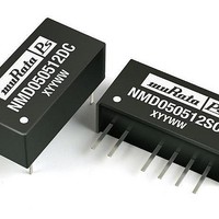
DC/DC Converters & Regulators 1W TWIN 5-5/15V DIP Twin Output
Manufacturer
Murata Power Solutions Inc
Series
NMDr
Datasheet
1.NMD050505SC.pdf
(4 pages)
Specifications of NMD050515DC
Output Power
0.5 W
Input Voltage Range
4.5 V to 5.5 V
Input Voltage (nominal)
5 V
Number Of Outputs
2
Output Voltage (channel 1)
5 V
Output Current (channel 1)
+/- 100 mA
Output Voltage (channel 2)
+/- 1.5 V
Output Current (channel 2)
+/- 100 mA
Isolation Voltage
1 KV
Package / Case Size
DIP
Output Voltage
5 V
Product
Isolated
Lead Free Status / RoHS Status
Lead free / RoHS Compliant


www.murata-ps.com
ISOLATION CHARACTERISTICS
Parameter
Isolation test voltage
Resistance
GENERAL CHARACTERISTICS
Parameter
Switching frequency
TEMPERATURE CHARACTERISTICS
Parameter
Specifi cation
Storage
Cooling
TEMPERATURE DERATING GRAPH
TECHNICAL NOTES
ISOLATION VOLTAGE
‘Hi Pot Test’, ‘Flash Tested’, ‘Withstand Voltage’, ‘Proof Voltage’, ‘Dielectric Withstand Voltage’ & ‘Isolation Test Voltage’ are all terms that relate to the same thing, a test voltage,
applied for a specifi ed time, across a component designed to provide electrical isolation, to verify the integrity of that isolation.
Murata Power Solutions NMD series of DC/DC converters are all 100% production tested at their stated isolation voltage. This is 1kVDC for 1 second.
A question commonly asked is, “What is the continuous voltage that can be applied across the part in normal operation?”
For a part holding no specifi c agency approvals, such as the NMD series, both input and output should normally be maintained within SELV limits i.e. less than 42.4V peak, or
60VDC. The isolation test voltage represents a measure of immunity to transient voltages and the part should never be used as an element of a safety isolation system. The part
could be expected to function correctly with several hundred volts offset applied continuously across the isolation barrier; but then the circuitry on both sides of the barrier must
be regarded as operating at an unsafe voltage and further isolation/insulation systems must form a barrier between these circuits and any user-accessible circuitry according to
safety standard requirements.
REPEATED HIGH-VOLTAGE ISOLATION TESTING
It is well known that repeated high-voltage isolation testing of a barrier component can actually degrade isolation capability, to a lesser or greater degree depending on materials,
construction and environment. The NMD series has toroidal isolation transformers, with no additional insulation between primary and secondary windings of enameled wire. While
parts can be expected to withstand several times the stated test voltage, the isolation capability does depend on the wire insulation. Any material, including this enamel (typically
polyurethane) is susceptible to eventual chemical degradation when subject to very high applied voltages thus implying that the number of tests should be strictly limited. We
therefore strongly advise against repeated high voltage isolation testing, but if it is absolutely required, that the voltage be reduced by 20% from specifi ed test voltage.
This consideration equally applies to agency recognized parts rated for better than functional isolation where the wire enamel insulation is always supplemented by a further
insulation system of physical spacing or barriers.
RoHS COMPLIANCE INFORMATION
www.murata-ps.com
1.5
1.0
0.5
0
0
Safe Operating Area
This series is compatible with RoHS soldering systems with a peak wave solder temperature of 300°C for 10 seconds. The pin termination fi nish
on the SIP package type is Tin Plate, Hot Dipped over Matte Tin with Nickel Preplate. The DIP types are Matte Tin over Nickel Preplate. Both
types in this series are backward compatible with Sn/Pb soldering systems.
For further information, please visit www.murata-ps.com/rohs
Ambient Temperature (ºC)
Conditions
Flash tested for 1 second
Viso= 500VDC
Conditions
All input types
Conditions
All output types
Free air convection
50
70°C
100
125ºC
150
TOLERANCE ENVELOPE
+10%
Isolated 1W Twin Output DC/DC Converters
Technical enquiries - email: mk@murata-ps.com, tel:
+5%
V
NOM
10
25
Output Load Current (%)
1000
Min.
Min.
Min.
-55
1
0
50
75
Typ.
Typ.
Typ.
100
NMD Series
KDC_NMDC.D03 Page 2 of 4
100
+2.5%
-2.5%
-7.5%
Max.
Max.
Max.
150
70
+44 (0)1908 615232
Units
Units
Units
VDC
kHz
GΩ
ºC
Related parts for NMD050515DC
Image
Part Number
Description
Manufacturer
Datasheet
Request
R

Part Number:
Description:
POWER OVER ETHERNET MODULE
Manufacturer:
Murata Power Solutions Inc
Datasheet:

Part Number:
Description:
POWER OVER ETHERNET MODULE
Manufacturer:
Murata Power Solutions Inc
Datasheet:

Part Number:
Description:
POWER OVER ETHERNET MODULE
Manufacturer:
Murata Power Solutions Inc
Datasheet:

Part Number:
Description:
POWER OVER ETHERNET MODULE
Manufacturer:
Murata Power Solutions Inc
Datasheet:

Part Number:
Description:
Power Inductors 2.2mH1.4A
Manufacturer:
Murata Power Solutions Inc
Datasheet:

Part Number:
Description:
Power Inductors 6.8uH 3.6A 20mOhm Toroidal SMT
Manufacturer:
Murata Power Solutions Inc
Datasheet:

Part Number:
Description:
Power Inductors Radial1.5mH 150mA
Manufacturer:
Murata Power Solutions Inc
Datasheet:
Part Number:
Description:
Power Inductors 680uH 2.2A 1.3MHz Radial PCB Mounting
Manufacturer:
Murata Power Solutions Inc
Datasheet:
Part Number:
Description:
Power Inductors 6.8mH0.5A
Manufacturer:
Murata Power Solutions Inc
Datasheet:
Part Number:
Description:
Power Inductors 470uH2.7A
Manufacturer:
Murata Power Solutions Inc
Datasheet:

Part Number:
Description:
Transformers 5Vin 5Vout 200mA 4000Vdc 1:1.33 turn
Manufacturer:
Murata Power Solutions Inc
Datasheet:

Part Number:
Description:
POWER SUPPLY
Manufacturer:
Murata Power Solutions Inc
Datasheet:

Part Number:
Description:
DPM LED MINI 2VDC 3.5DIG LP RED
Manufacturer:
Murata Power Solutions Inc
Datasheet:

Part Number:
Description:
CONV DC/DC 1W 5VIN 5VOUT SIP SGL
Manufacturer:
Murata Power Solutions Inc
Datasheet:

Part Number:
Description:
CONV DC/DC 1W 5VIN 3.3V SIP SGL
Manufacturer:
Murata Power Solutions Inc
Datasheet: