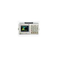
TDS3052C Tektronix, TDS3052C Datasheet - Page 2

TDS3052C
Manufacturer Part Number
TDS3052C
Description
Benchtop Oscilloscopes 500MHZ 5 GS/S 2 CH, COLOR DISPLAY
Manufacturer
Tektronix
Type
Digitalr
Datasheet
1.TDS3054C.pdf
(4 pages)
Specifications of TDS3052C
Equipment Type
Oscilloscope
Sampling Rate
5 GS/s
Bandwidth
500 MHz
Display Type
Color
Brand/series
TDS3000C Series
Configuration
Bench/Portable
Memory
10 Kpts
Number Of Channels
2
Sample Rate
5 GS/s
Lead Free Status / RoHS Status
Lead free / RoHS Compliant
Bandwidth
Calculated Rise
Time (typical)
Input Channels
External Trigger Input
Sample Rate on
Each Channel
Record Length
Vertical Resolution
Vertical Sensitivity, 1 MΩ
Vertical Sensitivity, 50 Ω
Input Coupling
Input Impedance
DC Gain Accuracy
Maximum Input Voltage, 1 MΩ
Maximum Input Voltage, 50 Ω
Position Range
Bandwidth Limit
Time Base Range
Time Base Accuracy
Input/Output Interfaces
Ethernet Port
USB Port
GPIB Port
RS-232-C Port
VGA Video Port
External Trigger Input
Acquisition Modes
DPO – Captures and displays complex waveforms,
random events and subtle patterns in actual signal
behavior. DPOs provide 3 dimensions of signal infor-
mation in real time: Amplitude, time and the distribu-
tion of amplitude over time.
Peak Detect – High frequency and random glitch
capture. Captures glitches as narrow as 1 ns (typical)
using acquisition hardware at all time base settings.
WaveAlert
channels and alerts the user to any waveform that
deviates from the normal waveform being acquired.
Sample – Sample data only.
Average – Waveform averaged, selectable
from 2 to 512.
Envelope – Min-max values acquired over one
or more acquisitions.
Single Sequence – Use the Single Sequence
button to capture a single triggered acquisition
sequence at a time.
Characteristics
TDS3000C Series Electrical Characteristics
®
– Monitors the incoming signals on all
TDS3012C
RJ-45 connector, supports 10Base-T LAN
Front-panel USB 2.0 host port
Supports USB flash drive
Full talk/listen modes, setting and measurements
(Optional with TDS3GV Communications Module)
DB-9 male connector, full talk/listen modes; control of all modes, settings and measurements
Baud rates up to 38,400
(Optional with TDS3GV Communications Module)
DB-15 female connector, monitor output for direct display on large VGA-equipped monitors
(Optional with TDS3GV Communications Module)
BNC connector, input impedence > 1 MΩ in parallel with 17 pF; max input voltage is 150 V
4 ns to 10 s
1.25 GS/s
100 MHz
20 MHz
3.5 ns
2
TDS3014C
4 ns to 10 s
1.25 GS/s
100 MHz
20 MHz
3.5 ns
Trigger System
Main Trigger Modes – Auto (supports Roll Mode for
40 ms/div and slower), Normal, Single Sequence.
B Trigger – Trigger after time or events.
Trigger After Time Range – 13.2 ns to 50 s.
Trigger After Events Range – 1 to 9,999,999 events.
Trigger Types
Edge – Conventional level-driven trigger. Positive or
negative slope on any channel. Coupling selections:
AC, DC, Noise Reject, HF Reject, LF Reject.
Video – Trigger on all lines or individual lines,
odd/even or all fields on NTSC, PAL, SECAM.
Extended Video – Trigger on specific lines in broad-
cast and non-broadcast (custom) standards and on
analog HDTV formats (1080i, 1080p, 720p, 480p).
Requires TDS3VID or TDS3SDI application module.
Pulse Width (or Glitch) – Trigger on a pulse width
<, >, =, ≠ to a selectable time limit ranging from
39.6 ns to 50 s.
4
Included on all models
20 MHz, 150 MHz
TDS3032C
2 ns to 10 s
+20 ppm over any 1 ms time interval
1 MΩ in parallel with 13 pF or 50 Ω
300 MHz
2.5 GS/s
+ 5 div
1.2 ns
150 V
5 V
2
RMS
1 mV/div to 10 V/div
RMS
1 mV/div to 1 V/div
with peaks at < 30 V
AC, DC, GND
with peaks at < 400 V
10 k points
9 bits
+2%
20 MHz, 150 MHz
TDS3034C
2 ns to 10 s
300 MHz
2.5 GS/s
1.2 ns
4
RMS
Digital Phosphor Oscilloscopes
Runt – Trigger on a pulse that crosses one
threshold but fails to cross a second threshold
before crossing the first again.
Slew Rate – Trigger on pulse edge rates that are
either faster or slower than a set rate. Edges can be
rising, falling or either.
Pattern – Specifies AND, OR, NAND, NOR when true
or false for a specific time.
State – Any logic state. Triggerable on rising or
falling edge of a clock. Logic triggers can be used
on combinations of 2 inputs (not 4).
Comm – Provides isolated pulse triggering required
to perform DS1/DS3 telecommunications mask
testing per ANSI T1.102 standard. Requires
TDS3TMT application module.
Alternate – Sequentially uses each active channel
as a trigger source.
20 MHz, 150 MHz
TDS3052C
1 ns to 10 s
500 MHz
5 GS/s
0.7 ns
2
TDS3000C Series
20 MHz, 150 MHz
TDS3054C
1 ns to 10 s
500 MHz
5 GS/s
0.7 ns
4
3


