ACD2000 Tektronix, ACD2000 Datasheet - Page 4
ACD2000
Manufacturer Part Number
ACD2000
Description
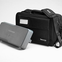
Benchtop Oscilloscopes SOFT CASE FOR SERIES OSCILLOSCOPES
Manufacturer
Tektronix
Type
Caser
Datasheet
1.ACD2000.pdf
(11 pages)
Specifications of ACD2000
Equipment Type
Case
Accessory Type
Large Nylon Soft Case
Lead Free Status / RoHS Status
Lead free / RoHS Compliant
For Use With
DPO/MSO2000 Series Oscilloscopes


4
Digital Phospor Oscilloscopes
MSO2000 Series • DPO2000 Series
Microprocessors, FPGAs, Analog-to-
Digital Converters (ADCs), and Digital-
to-Analog Converters (DACs) are all
examples of ICs that present unique
measurement challenges in today’s
embedded designs. The MSO2000
Series Mixed Signal Oscilloscopes offer
the addition of 16 digital channels. These
channels are tightly integrated into the
oscilloscope’s user interface, simplifying
operation and making it possible to
solve mixed signal issues easily.
Next Generation Digital
Waveform Display
In a continued effort to make mixed
signal oscilloscopes easy to use, the
MSO2000 Series has redefined the
way you view digital waveforms. One
common problem shared by both logic
analyzers and mixed signal oscilloscopes
is determining if data is a one or a zero
when zoomed in far enough that the
digital trace stays flat all the way across
the display. The MSO2000 has color-
coded the digital traces, displaying ones
in green and zeros in blue. In addition,
the MSO2000 displays white edges
around the transition points of digital
channels when there is uncertainty
between sample points. This acts as
a visual reminder that increasing the
sample rate on the next acquisition will
reveal higher frequency information than
your previous settings could acquire.
Channel setup on an MSO can often
be time consuming as compared to the
traditional oscilloscope. This process
often includes probing the device under-
test, labeling the channels, and positioning
the channels on screen. The MSO2000
simplifies this process by allowing the
user to group digital waveforms and
enter waveform labels using a USB
keyboard. By simply placing digital
Digital Phosphor Oscilloscopes • www.tektronix.com/mso2000 • www.tektronix.com/dpo2000
waveforms next to each other, they form
a group. Once a group is formed, you
can position all the channels contained
in that group together. This greatly reduces
the normal setup time associated with
positioning channels individually.
P6316 MSO Probe
This unique probe design offers two
eight-channel pods and simplifies the
process of connecting to the device-
under-test. When connecting to square
pins, the P6316 can connect directly to
8x2 square pin headers spaced on
tenth-inch centers. When more attach-
ment flexibility is required, you can use
the included flying lead sets and grab-
bers to clip onto surface mount devices
or test points. The P6316 offers
outstanding electrical characteristics
applying only 8 pF of loading with
101 kΩ input impedance.
FilterVu
Tired of being limited to a 20 MHz
bandwidth filter in your oscilloscope?
Output of DAC Signal) Notice how FilterVu
trace (yellow) which has removed all frequencies above 5.5 kHz. FilterVu also captures and displays high-
frequency glitches up to the full bandwidth of the oscilloscope in the background trace (orange).
TM
Variable Low-Pass Filter
TM
clearly shows the noise-free steps of the DAC in the foreground
Simply turn on FilterVu and adjust the
variable low-pass noise filter. Unlike
other variable low-pass filters, FilterVu
filters out the unwanted noise from your
signal while still capturing glitches and
other signal details up to the full band-
width of the oscilloscope. It does this
by showing two waveforms: a waveform
that can be filtered (foreground waveform)
and a glitch capture waveform (back-
ground waveform).
The filtered waveform uses a variable
low-pass filter to block out noise,
yielding a cleaner waveform to more
precisely locate signal edges and ampli-
tude levels. The result is improved
confidence in you cursor measure-
ments and cleaner documentation of
important signal attributes. When the
noise filter is adjusted to the lowest
available noise cutoff frequency, no
more than 1% of high-frequency content
that could cause the oscilloscope to
alias will pass through the filter.
The glitch capture waveform shows
signal details up to the full bandwidth
of the oscilloscope. The oscilloscope
captures pulses as narrow as 5 ns,
using peak detect min/max sampling,
protecting you from missing unexpected
glitches or other high-frequency events.
FilterVu is ideal for repetitive, nonrepetitive
and single-shot events.