169404 Tyco Electronics, 169404 Datasheet - Page 2
169404
Manufacturer Part Number
169404
Description
Crimping, Stripping, Cutting Tools & Drills CERTI-LOK DIE
Manufacturer
Tyco Electronics
Type
Crimping Dier
Datasheet
1.169404.pdf
(4 pages)
Specifications of 169404
Rohs Compliant
NA
Product
Tool Component
Lead Free Status / RoHS Status
Lead free / RoHS Compliant
For Use With
Hand Crimp Tool 169400
Lead Free Status / RoHS Status
Lead free / RoHS Compliant


three separate crimping closures that are color–coded
to match the color–coded terminal/splice for a given
wire range.
Note that Figure 1 indicates the number of dots that
will appear embossed on the crimped terminal or
splice. Observe the dot code on the finished crimp to
ensure that correct terminal/splice and die–closure
combination was used.
3. CRIMPING PROCEDURE
Determine your application requirements. Then, using
the table in Figure 1, make your selection according
to the following instructions:
Wire Size and Insulation Diameter – Make certain the
wire and insulation are within the specified range.
Wire Type and Strip Length – Using stranded wire,
strip it to the length shown. Do NOT crimp wire that
has cut or nicked strands.
Crimp terminal (or splice) as follows:
2
Crimping Dies 169404
of 4
C"
1. If necessary, install the dies according to the
instructions packaged with the tool.
C"
B"
B"
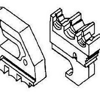
Typical PIDG and PLASTI-GRIP Terminals
PLASTI-GRIP
Terminal
Terminal
(Ring or Spade Receptacles)
PIDG
Figure 2
B" Equals Wire Barrel
C" Equals Insulation Barrel
C"
PIDG Insulating
Terminal Wire
Barrel Butts
Against Wire
Barrel Locator
Terminal Tongue
on Top of Locator
Restricting
B"
Tyco Electronics Corporation
First Crimp
2. Place terminal (or splice) in dies as shown in
Figure 2 or Figure 3.
3. Close tool handles until terminal or splice is held
firmly in place.
4. Insert properly stripped wire into terminal (or
splice) wire barrel “B” as shown in Figure 2 or
Figure 3.
5. Complete crimp by closing handles until ratchet
releases handles. Handles will open automatically
and crimped item may be removed.
6. To crimp other half of splice, remove it and
reposition uncrimped half in dies as shown in
Figure 3. Follow same procedure used to crimp
first half of splice. (If splice cannot be turned, turn
tool around.)
7. Inspect crimped terminal/splice. Check that
appropriate crimp code dot(s) appears on crimped
area of wire barrel. See Figure 1.
Conductor Butts
Against Splice
Wire Stop
Splice
Positioned
in Dies
B" Equals Wire Barrel
C" Equals Insulation Barrel
C"
PIDG Butt Splices
B"
Figure 3
Wire Stop
Window Indent
Conductor Butts
Against Splice
Wire Stop
Locator Seats in
Window Indent
of Splice
Second Crimp
408-6765
Rev
A