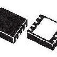
L5987 STMicroelectronics, L5987 Datasheet - Page 15

L5987
Manufacturer Part Number
L5987
Description
IC REG STEPDOWN 3A 8VFQFPN
Manufacturer
STMicroelectronics
Type
Step-Down (Buck)r
Datasheet
1.L5987TR.pdf
(41 pages)
Specifications of L5987
Internal Switch(s)
Yes
Synchronous Rectifier
No
Number Of Outputs
1
Voltage - Output
0.6 V ~ 18 V
Current - Output
3A
Frequency - Switching
250kHz
Voltage - Input
2.9 V ~ 18 V
Operating Temperature
-40°C ~ 150°C
Mounting Type
Surface Mount
Package / Case
8-VFQFN, Exposed Pad
Output Voltage
0.6 V
Output Current
3 A
Output Power
1.5 W
Input Voltage
2.9 V to 18 V
Switching Frequency
250 KHz
Mounting Style
SMD/SMT
Duty Cycle (max)
100 %
Low Dropout Operation
100 % duty cycle
Lead Free Status / RoHS Status
Lead free / RoHS Compliant
Available stocks
Company
Part Number
Manufacturer
Quantity
Price
L5987
5.7
5.8
Maximum DC output current L5987A (HSOP8)
The L5987A can manage DC output currents up to 3 A and the rated RMS current of its
internal power switch is 3 A. So the L5987A can deliver 3 A with 100% of duty cycle.
Maximum DC output current L5987 (VFQFPN)
The L5987 can manage DC output currents up to 3 A. However the rated RMS current of its
internal power switch is 2.5 A.
Since the current flows through the integrated power element only during the on time, the
RMS value is given by:
Equation 3
Where D is the duty cycle (V
Considering I
Equation 4
In
duty cycles lower than 69%, the RMS current does not limit the maximum DC output current
of 3 A. For duty cycles higher than the 69% the maximum DC output current is limited by the
RMS current to:
Equation 5
In order to have a more accurate calculation of the maximum DC output current, the
complete expression for the duty cycle can be adopted, considering the voltage drop across
the power MOSFET, the series resistance of the inductor and the forward voltage of the
rectification diode. The duty cycle results:
Equation 6
where I
For example with V
DCR = 30 mΩ, the duty results D = 78%, so according to
output current is 2.83 A, which is higher than desired current.
Figure 9
O
is the desired DC output current.
the maximum DC output current is reported as a function of the duty cycle. For
O
= 3 A, the maximum duty cycle that can be managed is:
IN
= 5 V, V
I
O
O MAX
OUT
/V
,
Doc ID 14972 Rev 3
IN
D
= 3.3 V, I
).
=
=
D
2.5
------- -
V
--------------------------------------------------------- -
V
I
D
RMS
OUT
IN
=
+
I
------------
O
2
RMS
I
V
+
2
O
=
= 2.6 A,
F
V
[ ]
I
–
A
F
O
=
R
+
⋅
DSON
69%
DCR I
D
R
if D 69%
DS(on)
⋅
⋅
I
O
O
≥
Equation 5
= 220 mΩ, V
Functional description
the maximum DC
F
= 0.35 V and
15/41


