6539S-1-202 Bourns Inc., 6539S-1-202 Datasheet
6539S-1-202
Manufacturer Part Number
6539S-1-202
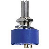
Description
POT 2.00K OHM 7/8" PRECISION
Manufacturer
Bourns Inc.
Series
6539r
Type
Variabler
Specifications of 6539S-1-202
Adjustment Type
Top Adjustment
Resistance (ohms)
2K
Power (watts)
1W
Tolerance
±15%
Temperature Coefficient
±500ppm/°C
Number Of Turns
Single
Rotation
Continuous
Resistive Material
Conductive Plastic
Termination Style
Solder Turret
Actuator Length
12.70mm
Actuator Type
Round Shaft
Actuator Diameter
3.17mm
Package / Case
Round - 0.875" Dia x 0.500" H (22.23mm x 12.70mm)
Track Resistance
2kohm
Track Taper
Linear
No. Of Turns
1
Resistance Tolerance
± 15%
Power Rating
1W
Terminal Type
Servo Mount
Resistance
2 KOhms
Shaft Type
Round / Plain
Shaft Length
12.7 mm
Dimensions
22.23 mm Dia.
Product
Precision Potentiometers
Termination Type
Through Hole
Resistance Min
2ohm
Rohs Compliant
Yes
Filter Terminals
Through Hole
Potentiometer Mounting
Servo
No. Of Gangs
1
Lead Free Status / RoHS Status
Lead free / RoHS Compliant
Lead Free Status / RoHS Status
Lead free / RoHS Compliant, Lead free / RoHS Compliant
Available stocks
Company
Part Number
Manufacturer
Quantity
Price
Company:

Part Number:
6539S-1-202
Manufacturer:
BOURNS
Quantity:
1 000


Standard Resistance Range ..............1 K to 100 K ohms ..................1 K to 100 K ohms
Total Resistance Tolerance ................±15 % ......................................±15 %
Independent Linearity ........................±2.0 % ......................................±2.0 %
Effective Electrical Angle ....................340 ° +3 °..................................340 ° +3 °
End Voltage ........................................0.5 % maximum ......................0.5 % maximum
Output Smoothness............................0.1 % ........................................0.1 %
Dielectric Withstanding Voltage (MIL-STD-202, Method 301)
Power Rating (Voltage Limited By Power Dissipation or 300 VAC, Whichever is Less)
Insulation Resistance (500 VDC) ........500 megohms minimum ..........500 megohms minimum
Resolution ..........................................Essentially infinite ....................Essentially infinite
Operating Temperature Range ..........+1 °C to +125 °C ......................-40 °C to +125 °C
Storage Temperature Range ..............-65 °C to +125 °C ....................-65 °C to +125 °C
Temperature Coefficient
Over Storage Temperature Range ......±500 ppm/°C maximum ..........±500 ppm/°C maximum
Vibration..............................................15 G ..........................................15 G
Shock..................................................50 G ..........................................50 G
Load Life ............................................1,000 hours, 1 watt ..................1,000 hours, 1 watt
Rotational Life (No Load)....................10,000,000 shaft revolutions ....10,000,000 shaft revolutions
Moisture Resistance (MIL-STD-202, Method 106)
IP Rating ............................................IP 40 ........................................IP 40
Mechanical Angle ..........................................................Continuous, Stops (340 ° +8 °, -0 °) available
Torque (Starting & Running)
Shaft Runout..................................................................................................0.13 mm (0.005 in.) T.I.R.
Lateral Runout ...............................................................................................0.08 mm (0.003 in.) T.I.R.
Shaft End Play ...............................................................................................0.13 mm (0.005 in.) T.I.R.
Shaft Radial Play ...........................................................................................0.13 mm (0.005 in.) T.I.R.
Pilot Diameter Runout .................................................................................0.06 mm (0.0025 in.) T.I.R.
Backlash ........................................................................................................................0.1 º maximum
Weight ........................................................18 gm (6539 Servo Mount), 24 gm (6639 Bushing Mount)
Terminals......................................................................................................................Rear Turret Type
Soldering Condition
Marking .................................................Manufacturer’s name and part number, resistance value and
Ganging (Multiple Section Pots) ..................................................................................1 cup maximum
Hardware (6639 only)..................................One lockwasher (H-37-2) and one mounting nut (H-38-2)
1
2
BOLDFACE LISTINGS ARE IN STOCK AND READILY
AVAILABLE THROUGH DISTRIBUTION.
FOR OTHER OPTIONS CONSULT FACTORY.
At room ambient: +25 °C nominal and 50 % relative humidity, except as noted.
2.82 N-cm (4.0 oz.-in.) max. at -40 °C.
Recommended Part Numbers
Electrical Characteristics
Environmental Characteristics
Mechanical Characteristics
Sea Level........................................750 VAC minimum ....................750 VAC minimum
+70 °C ............................................1.0 watt ....................................1.0 watt
+125 °C ..........................................0 watt........................................0 watt
Wiper Bounce ................................0.1 millisecond maximum ........0.1 millisecond maximum
Total Resistance Shift ....................±10 % ......................................±10 %
Voltage Ratio Shift..........................±0.5 % ......................................±0.5 %
Wiper Bounce ................................0.1 millisecond maximum ........0.1 millisecond maximum
Total Resistance Shift ....................±5 % ........................................±5 %
Voltage Ratio Shift..........................±0.5 % ......................................±0.5 %
Total Resistance Shift ....................±10 % ......................................±10 %
Total Resistance Shift ....................±10 % maximum ......................±10 % maximum
Total Resistance Shift ....................±15 % ......................................±15 %
Mounting.............................................................................170-200 N-cm (15-18 lb.-in.) maximum
Manual Soldering................................96.5Sn/3.0Ag/0.5Cu solid wire or no-clean rosin cored wire
Wave Soldering ........................................................96.5Sn/3.0Ag/0.5Cu solder with no-clean flux
Wash processes ..................................................................................................Not recommended
Part Number
6539S-1-102
6539S-1-502
6539S-1-103
2
.....................................................................0.40 N-cm (0.5 oz.-in.) max.
Resistance
1,000
5,000
10,000
1
(Ω)
1
6539 Servo Mount
1
tolerance, linearity tolerance, wiring diagram, and date code.
6639S-1-102 6639S-301-102
6639S-1-202
6639S-1-502 6639S-301-502
6639S-1-103 6639S-301-103
6639S-1-203
Continuous Turn
6539/6639 - Precision Potentiometer
Features
Essentially infinite resolution
Excellent rotational life
High quality, rugged construction
General purpose applications
Non-standard features available
Cost and space saving
Part Numbers
370 °C (700 °F) max. for 3 seconds
260 °C (500 °F) max. for 5 seconds
6639 Bushing Mount
Mechanical Stops
is shipped with potentiometer.
Customers should verify actual device performance in their specific applications.
Resistance
10,000
20,000
1,000
2,000
5,000
(Ω)
*RoHS Directive 2002/95/EC Jan 27 2003 including Annex
22.23
(.875)
6639
6539
DIA.
65/6639
(.875)
22.23
Product Dimensions
DIA.
Specifications are subject to change without notice.
CCW
11.25 ± .38
(.443±.015)
(.125)
3.18
1
(.062)
(.500 ± .015)
1.57
12.70 ± .38
TOLERANCES: EXCEPT WHERE NOTED
DECIMALS: .XX ±
FRACTIONS: ±1/64
DIMENSIONS:
(.125)
3.18
CLOCKWISE
30 °± 3 °
TYP.
CW
3
3/8 " - 32 UNEF
45 ° ± 5° ± (.010) CHAMFER
(IN.)
SLOT (.047) X (.063)
MM
2
2
(.2497+.0000/-.0003)
(.062)
(.020)
1.57
6.342+.000/-.008
.51
(.062)
WIPER
1.57
(.062)
(.4062+.000/-.002)
(.875 ± .03)
10.317+.000/-.051
22.23 ± .76
1.19
1.57
(.020)
DIA. SHAFT
1
REF
.51
.XXX ±
(.375 ± .031)
9.53 ± .79
.25
(.1248+.0000/-.0003)
3.170 +.000/-.008
1.60
(.750+.0000/-.0005)
19.050+ 000/-.012
45 ° ± 5 ° x (.010)
CHAMFER
(.010)
(.005)
.13
3
REF
DIA. SHAFT
.25
(.500 ± .031)
12.70 ± .79
CW
(.19)
4.83
DIA.
(.780)
19.81
R
DIA.
.25
Related parts for 6539S-1-202
Image
Part Number
Description
Manufacturer
Datasheet
Request
R

Part Number:
Description:
POT 5.00K OHM 7/8" PRECISION
Manufacturer:
Bourns Inc.
Datasheet:
Part Number:
Description:
POT 1K OHM 7/8" PRECISION
Manufacturer:
Bourns Inc.
Datasheet:
Part Number:
Description:
POT 20K OHM 7/8" PRECISION
Manufacturer:
Bourns Inc.
Datasheet:
Part Number:
Description:
RES,Conductive Plastic,50KOhms,15+/-% Tol
Manufacturer:
Bourns Inc.
Datasheet:

Part Number:
Description:
NICKEL CADMIUM BATTERY, 2.4V, 2.4AH
Manufacturer:
DANTONA INDUSTRIES

Part Number:
Description:
Manufacturer:
Bourns, Inc.
Datasheet:
Part Number:
Description:
11mm Potentiometer
Manufacturer:
Bourns, Inc.
Datasheet:
Part Number:
Description:
Manufacturer:
Bourns, Inc.
Datasheet:
Part Number:
Description:
Manufacturer:
Bourns, Inc.
Datasheet:
Part Number:
Description:
Manufacturer:
Bourns, Inc.
Datasheet:
Part Number:
Description:
5/16 Round Trimming Potentiometer
Manufacturer:
Bourns, Inc.
Datasheet:
6539S-1-202 Summary of contents
Page 1
... N-cm (4.0 oz.-in.) max. at -40 °C. Recommended Part Numbers Resistance Part Number (Ω) 6539S-1-102 1,000 6539S-1-502 5,000 6539S-1-103 10,000 BOLDFACE LISTINGS ARE IN STOCK AND READILY AVAILABLE THROUGH DISTRIBUTION. FOR OTHER OPTIONS CONSULT FACTORY. Features Essentially infinite resolution Excellent rotational life High quality, rugged construction ...
Page 2
Precision Potentiometer Panel Thickness Dimensions (For Bushing Mount Only) 10.41 ± .08 DIA. (.410 ± .003) REV. 10/08 Specifications are subject to change without notice. Customers should verify actual device performance in their specific applications. HEX NUT 7.42 ...