145-0694-002 Emerson Network Power, 145-0694-002 Datasheet - Page 3
145-0694-002
Manufacturer Part Number
145-0694-002
Description
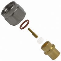
CONN SMK PLUG SEMI-RIGID STR SLD
Manufacturer
Emerson Network Power
Series
SMKr
Datasheet
1.145-0694-002.pdf
(3 pages)
Specifications of 145-0694-002
Connector Style
SMK
Connector Type
Plug, Male Pins
Contact Termination
Clamp and Solder
Impedance
50 Ohm
Mounting Type
Free Hanging (In-Line)
Fastening Type
Threaded
Cable Group
RG-402 (.141" Semi Rigid)
Frequency - Max
40GHz
Color
Gold, Silver
Frequency-max
40GHz
Body Style
Straight
Cable Type
0.141 Semi Rigid
Features
With contact, slide on nut, passivated
Frequency Range
0 GHz to 40 GHz
Housing Material
Stainless Steel
Length
2.92 mm
Operating Temperature Range
- 65 C to + 165 C
Rf Series
SMK
Product
Various Connectors
Contact Plating
Gold
Shell Plating
Gold
Termination Style
Solder Lug
Maximum Frequency
40 GHz
Lead Free Status / RoHS Status
Lead free / RoHS Compliant
Lead Free Status / RoHS Status
Lead free / RoHS Compliant, Lead free / RoHS Compliant
Other names
J690


SMK - 50 Ohm Connectors (2.92mm)
INCHES (MILLIMETERS)
SMK Solder Type Straight Plugs For Semi-rigid Cable
6
1
2
3
4
5
•
COUPLING NUT
Johnson Components
CUSTOMER DRAWINGS AVAILABLE UPON REQUEST
BEAD ASSEMBLY TOOL
.000 - .005 RECESSION
BEAD TO BODY
BODY
™
• P.O. Box 1732 • Waseca, MN 56093-0832 • 1-800-247-8256 • Fax: 507-833-6287 • www.johnsoncomponents.com
BEAD
SEAL RING
CABLE SOLDERING VISE
BEAD
CONTACT
VISE STOP
PLUNGER
2
1
2
3
3
4
5
6
Identify connector parts (5 piece parts) and tools (5 tools.)
Strip cable jacket and dielectric to dimension shown.
Place center contact onto center conductor. Slide con-
tact soldering tool onto contact. Clamp the cable con-
tact and tool into cable soldering vise and solder con-
tact to center conductor. High temperature solder,
such as 95/5 Sn/Ag is recommended so that contact
solder joint remains stable during body soldering op-
eration. Solder paste is recommended for the contact
solder joint to minimize excess solder. The assembled
dimension should be as shown.
Remove excess solder from contact with a sharp blade
and clean contact. Check for presence of excess sol-
der by sliding body soldering tool over the contact. Re-
move soldering tool.
Place connector nut and body on cable. Place con-
nector body soldering tool over contact and thread the
coupling nut and connector body firmly to the tool. Place
cable subassembly into cable soldering vise. Clamp
cable and soldering tool securely to insure the cable
dielectric expansion will not disturb the cable in the vise
during soldering. Place hot soldering iron on the con-
nector body sleeve and apply solder from the opposite
side. A low temp solder, such as 60/40 Sn/Pb is rec-
ommended for the body solder joint. Allow the soldered
joint to cool and remove from fixture. Check contact
location to the body. The best electrical results are
achieved when the contact location is within a toler-
ance of .060 +/- .001.
Place bead onto neck portion of the tool. Thread Bead
Assembly tool firmly into the coupling nut. Push the
tool's plunger between your thumb and fingers to as-
semble the bead. Check bead location. Assemble seal
ring onto body.
Contact Soldering Tool
Semi-Rigid Cable Vise
Body Soldering Tool
Cable Clamp Insert
Bead Assy. Tool
TOOL
Vise Stop
VISE STOP
CABLE SOLDERING VISE
P/N 140-0000-962
145-0693-001/002
(FOR .086 SEMI-RIGID)
140-0000-962
140-0000-968
140-0000-957
140-0000-960
140-0000-958
140-0000-964
ASSEMBLY
BEAD
TOOL
145-0694-001/002
(FOR .141 SEMI-RIGID)
140-0000-962
140-0000-968
140-0000-957
140-0000-961
140-0000-959
140-0000-965
Related parts for 145-0694-002
Image
Part Number
Description
Manufacturer
Datasheet
Request
R

Part Number:
Description:
RF Connectors STRT PLG .141S/R GLD
Manufacturer:
Emerson Network Power

Part Number:
Description:
CONN SMK JACK RCPT 2-HOLE FLANGE
Manufacturer:
Emerson Network Power
Datasheet:

Part Number:
Description:
CONN SMK PLUG SEMI-RIGID STR SLD
Manufacturer:
Emerson Network Power

Part Number:
Description:
RF Connectors STRT PLG .086S/R GLD
Manufacturer:
Emerson Network Power

Part Number:
Description:
FPGA - Field Programmable Gate Array 3.1K LUTs 145 IO 1.2 V -4 Spd
Manufacturer:
Lattice

Part Number:
Description:
AC/DC Front end 12Vo 36A 12Vsb Standard Airflow
Manufacturer:
Emerson Network Power

Part Number:
Description:
POWER SUPPLY DIN 24VDC 10A
Manufacturer:
Emerson Network Power
Datasheet:

Part Number:
Description:
POWER SUPPLY SGL 48VOUT 40W 3X5"
Manufacturer:
Emerson Network Power
Datasheet:

Part Number:
Description:
POWER SUP MED&ITE 48V 45W 2"X4"
Manufacturer:
Emerson Network Power
Datasheet:

Part Number:
Description:
POWER SUPPLY 60W 12V OUT
Manufacturer:
Emerson Network Power
Datasheet:

Part Number:
Description:
POWER SUPPLY 60W 48V OUT
Manufacturer:
Emerson Network Power
Datasheet:

Part Number:
Description:
POWER SUPPLY 60W 15V OUT
Manufacturer:
Emerson Network Power
Datasheet:

Part Number:
Description:
POWER SUPPLY TRPL 3.3/5/12V 40W
Manufacturer:
Emerson Network Power
Datasheet:

Part Number:
Description:
POWER SUPPLY SWITCHER 24V 40W
Manufacturer:
Emerson Network Power
Datasheet:

Part Number:
Description:
Linear & Switching Power Supplies 24V output 25W 2A Medical &Non-Medical
Manufacturer:
Emerson Network Power
Datasheet: