ENERGY-HARVEST-RD Silicon Laboratories Inc, ENERGY-HARVEST-RD Datasheet
ENERGY-HARVEST-RD
Specifications of ENERGY-HARVEST-RD
Available stocks


Related parts for ENERGY-HARVEST-RD


ENERGY-HARVEST-RD Summary of contents
Page 1
... The leakage current of the energy harvesting supply, when enabled, is approximately 3 µA and is cancelled out by as little as 50 lux shining into the solar cell. This allows the energy harvesting supply to power the system for approximately 7 days in a dark closet (in the ON position) or indefinitely if there is a periodic light source that replenishes the lost energy ...
Page 2
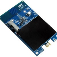
AN588 3. Hardware Overview Figure 2 and Figure 3 identify the major components of the Sensor Node and the USB Dongle. Both devices come preloaded with the firmware for the demo application. When using the demo application, ensure that the ...
Page 3
... Place the S2 power source switch in the SOLAR position. It takes seconds for the sensor node to charge a 100 µF capacitor from the solar cell (200 lx minimum), then use the stored energy for a full POR. The green LED should blink 3 times to indicate that the sensor node is powered up. Three red LED blinks indicate that there is not enough energy in the system to start up, and that the sensor node needs to be charged ...
Page 4
... USB Dongle. The USB Dongle will blink green each time it successfully receives a valid packet. 8. The Energy Harvesting Application will designate the first Sensor Node to associate as Node nodes are allowed to associate. Cover the solar cell, or shine a flashlight into it to see it dynamically update the light level in the application ...
Page 5
... Packet tab, a list of all received packets is displayed. Selecting a packet will decode the raw data and display the extracted information in the VBAT, TEMP, and LIGHT_LEVEL fields. Figure 7. Energy Harvesting Demo (NodeInfo View) 11. On the NodeInfo tab, a summary of the latest sensor data is displayed in a text format. ...
Page 6
... The energy harvesting system can remain in a dark closet for 1 week before all the stored energy is depleted. When the system is going to be placed in a dark area for a prolonged period of time best to place the S2 switch in “OFF” mode, which activates the “ship mode” and disconnects the battery from the system. This allows the system to hold its current state until the S2 switch is placed in the “ ...
Page 7
... RF connection once per button press. The light level is transmitted once a second for three minutes. One of the distinguishing features of the Si1012 which makes it excellent for energy harvesting applications is its ultra low power consumption both in sleep and active modes. Figure 9 shows a simplified activity profile for the active mode (RF packet transmission once a second). The peak current when the RF transmitter is enabled and the average current over the three minute time interval is 51 µ ...
Page 8
... OFF position. The system will hold its charge indefinitely in the OFF position. If the energy in the system ever gets depleted, then it may be quickly charged (30 minutes) by plugging in a ToolStick Base Adapter and setting the power source switch to USB ...
Page 9
Schematic Rev. 0.2 AN588 9 ...
Page 10
AN588 10 Rev. 0.2 ...
Page 11
Rev. 0.2 AN588 11 ...
Page 12
... Should Buyer purchase or use Silicon Laboratories products for any such unintended or unauthorized ap- plication, Buyer shall indemnify and hold Silicon Laboratories harmless against all claims and damages. Silicon Laboratories and Silicon Labs are trademarks of Silicon Laboratories Inc. Other products or brandnames mentioned herein are trademarks or registered trademarks of their respective holders 12 Rev ...