142-1701-611 Emerson Network Power, 142-1701-611 Datasheet - Page 2
142-1701-611
Manufacturer Part Number
142-1701-611
Description
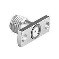
CONN JACK .015" GOLD SMA
Manufacturer
Emerson Network Power
Series
SMAr
Datasheet
1.142-1701-611.pdf
(4 pages)
Specifications of 142-1701-611
Connector Style
SMA
Connector Type
Jack, Female Sockets
Contact Termination
Solder
Impedance
50 Ohm
Mounting Type
Panel Mount, Flange (2 Hole)
Fastening Type
Threaded
Frequency - Max
26.5GHz
Frequency-max
26.5GHz
Product
Connector
Rf Series
SMA
Gender
Receptacle
Shell Plating
Gold
Body Style
Straight
Maximum Frequency
26.5 GHz
Lead Free Status / RoHS Status
Lead free / RoHS Compliant
Features
-
Color
-
Cable Group
-
Lead Free Status / Rohs Status
Lead free / RoHS Compliant
Other names
1421701611
J562
J562


SMA - 50 Ohm Connectors
Field Replaceable - Application Notes
The field replaceable style of connector is known by many names in the industry, such as MIC launcher, hermetic seal launcher, spark plug
launcher, etc. Some types, such as those known as “spark plugs”, have the hermetic seal incorporated into the connector. These types
require special welding to install and can not be replaced without destroying the hermeticity of the circuit housing. True field replaceable
connectors, such as those manufactured by Johnson Components
incorporated into the connector design, the connector can be removed and replaced without destroying the hermetic seal or the hermeticity
of the circuit housing.
All of the above mentioned connector types perform the same basic function - creating a transition from microstrip circuitry to a coaxial
transmission line. Whenever possible, the hermetic seal pin diameter should be chosen as close as possible to the microstrip trace width.
For optimum electrical performance, the transition from the hermetic seal to the microstrip trace must be properly compensated. Compen-
sation involves adjusting the microstrip trace width to minimize any impedance discontinuities found in the transition area.
The plot shown below is representative of the typical return loss of an Johnson Components
data shown below, a test fixture is created using the appropriate Johnson Components
thick spacer plate with the hermetic seal mounted flush to both surfaces. Two connectors are mounted back to back around the fixture and
the VSWR of this test assembly is measured. The return loss data shown is equivalent to the square root of the measured VSWR of the
test assembly. Since the connectors tested are of identical design, it can be stated with fair accuracy that the data shown represents the
response of a single field replaceable connector and its transition to the hermetic seal.
Although Johnson Components
expected to be less than 1.1 + .01f (f in GHz). A VSWR specification is not stated because an industry standard method for testing field
replaceable connectors does not exist. The actual performance of the connector is dependent upon the application for the following
reasons:
As always, quotes for non-standard field replaceable connectors and/or hermetic seals are welcome.
1.
2.
3.
The choice of hermetic seal to be used by the customer is not specified by the connector manufacturer. Hermetic seals produced
by different manufacturers will not have the same electrical characteristics. For optimum electrical performance, Johnson Compo-
nents
.015 (0.38), .018 (0.46) and .020 (0.51). Custom hermetic seal configurations can be quoted.
seal and machined housing do not always guarantee an optimum transition to the connector. Some manufacturers recommend
an additional counterbore in the circuit housing to accommodate a solder washer during installation of the seal. Johnson Compo-
nents
discontinuities may be created.
different methods of hermetic seal mounting and seal pin to microstrip trace attachment are used in the industry. Johnson
Components
It is recommended that the hermetic seal be mounted flush with the circuit housing. Tolerance variations between the hermetic
The transition between the hermetic seal pin and the microstrip trace will affect electrical performance, as stated above. Several
Johnson Components
TM
TM
recommends the use of our standard 142-1000-001, 002, 003 and 004 hermetic seals for pin diameters of .012 (0.30),
does not recommend this type of installation because if the counterbore is not completely filled with solder, electrical
TM
can not recommend one method over the other as this is dependent upon the customer’s application.
TM
TM
does not publish a VSWR specification for field replaceable connectors, typical connector VSWR can be
• P.O. Box 1732 • Waseca, MN 56093-0832 • 1-800-247-8256 • Fax: 507-833-6287 • www.johnsoncomponents.com
TM
, are easy to install and replace. Because the hermetic seal is not
TM
hermetic seal. The fixture consists of a suitably
TM
field replaceable connector. To produce the
CUSTOMER DRAWINGS AVAILABLE UPON REQUEST
INCHES (MILLIMETERS)
Related parts for 142-1701-611
Image
Part Number
Description
Manufacturer
Datasheet
Request
R

Part Number:
Description:
CONN JACK FLANGE MOUNT GOLD
Manufacturer:
Emerson Network Power
Datasheet:


Part Number:
Description:
CONN JACK RECEPT 4HOLE FLNG MNT
Manufacturer:
Emerson Network Power

Part Number:
Description:
CONN JACK .015 PIN .016 CIR.
Manufacturer:
Emerson Network Power
Datasheet:

Part Number:
Description:
CONN JACK .018" NICKEL SMA
Manufacturer:
Emerson Network Power

Part Number:
Description:
RF Connectors PC END BLKHD JCK GLD .074" BOARDS
Manufacturer:
Emerson Network Power

Part Number:
Description:
AC/DC Front end 12Vo 36A 12Vsb Standard Airflow
Manufacturer:
Emerson Network Power

Part Number:
Description:
POWER SUPPLY DIN 24VDC 10A
Manufacturer:
Emerson Network Power
Datasheet:

Part Number:
Description:
POWER SUPPLY SGL 48VOUT 40W 3X5"
Manufacturer:
Emerson Network Power
Datasheet:

Part Number:
Description:
POWER SUP MED&ITE 48V 45W 2"X4"
Manufacturer:
Emerson Network Power
Datasheet:

Part Number:
Description:
POWER SUPPLY 60W 12V OUT
Manufacturer:
Emerson Network Power
Datasheet:

Part Number:
Description:
POWER SUPPLY 60W 48V OUT
Manufacturer:
Emerson Network Power
Datasheet:

Part Number:
Description:
POWER SUPPLY 60W 15V OUT
Manufacturer:
Emerson Network Power
Datasheet:

Part Number:
Description:
POWER SUPPLY TRPL 3.3/5/12V 40W
Manufacturer:
Emerson Network Power
Datasheet:

Part Number:
Description:
POWER SUPPLY SWITCHER 24V 40W
Manufacturer:
Emerson Network Power
Datasheet: