142-1701-616 Emerson Network Power, 142-1701-616 Datasheet - Page 220
142-1701-616
Manufacturer Part Number
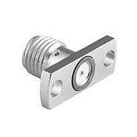
142-1701-616
Description
CONN JACK .015" NICKEL SMA
Manufacturer
Emerson Network Power
Series
SMAr
Specifications of 142-1701-616
Connector Style
SMA
Connector Type
Jack, Female Sockets
Contact Termination
Solder
Impedance
50 Ohm
Mounting Type
Panel Mount, Flange (2 Hole)
Fastening Type
Threaded
Frequency - Max
26.5GHz
Frequency-max
26.5GHz
Product
Connector
Lead Free Status / RoHS Status
Lead free / RoHS Compliant
Features
-
Color
-
Cable Group
-
Lead Free Status / Rohs Status
Lead free / RoHS Compliant
Other names
1421701616
J563
J563


220
Assembly Instructions
INCHES (MILLIMETERS) • CUSTOMER DRAWINGS AVAILABLE ON REQUEST
SMK Solder Type Straight Plugs for Semi-Rigid Cable
Connectivity Solutions
BEAD ASSEMBLY TOOL
.000 - .005 RECESSION
BEAD TO BODY
BEAD
Tel: 800-247-8256
PLUNGER
•
Fax: 507-833-6287
Contact Soldering Tool
4.
Semi-Rigid Cable Vise
1.
2.
3.
5.
6.
Body Soldering Tool
Cable Clamp Insert
Bead Assy. Tool
•
Identify connector parts (5 piece parts) and tools (5 tools.)
Strip cable jacket and dielectric to dimension shown.
Place center contact onto center conductor. Slide contact
soldering tool onto contact. Clamp the cable contact
and tool into cable soldering vise and solder contact to
center conductor. High temperature solder, such as
95/5 Sn/Ag is recommended so that contact solder joint
remains stable during body soldering operation. Solder
paste is recommended for the contact solder joint
to minimize excess solder. The assembled contact
dimension should be as shown.
Remove excess solder from contact with a sharp blade
and clean contact. Check for presence of excess
solder by sliding body soldering tool over the contact.
Remove soldering tool.
Place connector nut and body on cable. Place connector
body soldering tool over contact and thread the
coupling nut and connector body firmly to the tool. Place
cable subassembly into cable soldering vise. Clamp
cable and soldering tool securely to insure the cable
dielectric expansion will not disturb the cable in the vise
during soldering. Place hot soldering iron on the
connector body sleeve and apply solder from the
opposite side. A low temp solder, such as 60/40 Sn/Pb
is recommended for the body solder joint. Allow the
soldered joint to cool and remove from fixture. Check
contact location to the body. The best electrical results
are achieved when the contact location is within a tol-
erance of .060 +/- .001.
Place bead onto neck portion of the tool. Thread Bead
Assembly tool firmly into the coupling nut. Push the tool’s
plunger between your thumb and fingers to assemble
the bead. Check bead location. Assemble seal ring onto
body.
www.EmersonNetworkPower.com/connectivity
Vise Stop
TOOL
145-0693-001/002 145-0694-001/002
(for .086 Semi-Rigid)
140-0000-962
140-0000-968
140-0000-957
140-0000-960
140-0000-958
140-0000-964
(for .141 Semi-Rigid)
140-0000-962
140-0000-968
140-0000-957
140-0000-961
140-0000-959
140-0000-965
Related parts for 142-1701-616
Image
Part Number
Description
Manufacturer
Datasheet
Request
R

Part Number:
Description:
CONN JACK FLANGE MOUNT GOLD
Manufacturer:
Emerson Network Power
Datasheet:


Part Number:
Description:
CONN JACK RECEPT 4HOLE FLNG MNT
Manufacturer:
Emerson Network Power

Part Number:
Description:
CONN JACK .015 PIN .016 CIR.
Manufacturer:
Emerson Network Power
Datasheet:

Part Number:
Description:
CONN JACK .018" NICKEL SMA
Manufacturer:
Emerson Network Power

Part Number:
Description:
RF Connectors PC END BLKHD JCK GLD .074" BOARDS
Manufacturer:
Emerson Network Power

Part Number:
Description:
AC/DC Front end 12Vo 36A 12Vsb Standard Airflow
Manufacturer:
Emerson Network Power

Part Number:
Description:
POWER SUPPLY DIN 24VDC 10A
Manufacturer:
Emerson Network Power
Datasheet:

Part Number:
Description:
POWER SUPPLY SGL 48VOUT 40W 3X5"
Manufacturer:
Emerson Network Power
Datasheet:

Part Number:
Description:
POWER SUP MED&ITE 48V 45W 2"X4"
Manufacturer:
Emerson Network Power
Datasheet:

Part Number:
Description:
POWER SUPPLY 60W 12V OUT
Manufacturer:
Emerson Network Power
Datasheet:

Part Number:
Description:
POWER SUPPLY 60W 48V OUT
Manufacturer:
Emerson Network Power
Datasheet:

Part Number:
Description:
POWER SUPPLY 60W 15V OUT
Manufacturer:
Emerson Network Power
Datasheet:

Part Number:
Description:
POWER SUPPLY TRPL 3.3/5/12V 40W
Manufacturer:
Emerson Network Power
Datasheet:

Part Number:
Description:
POWER SUPPLY SWITCHER 24V 40W
Manufacturer:
Emerson Network Power
Datasheet: