RCL121810K0JNEK Vishay, RCL121810K0JNEK Datasheet - Page 3
RCL121810K0JNEK
Manufacturer Part Number
RCL121810K0JNEK
Description
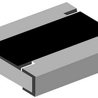
RES 10K OHM 1W 5% 1218 WIDE
Manufacturer
Vishay
Series
RCLr
Specifications of RCL121810K0JNEK
Resistance (ohms)
10K
Number Of Terminations
2
Package / Case
1812 (4532 Metric) Wide, 1218 (3245 Metric)
Power (watts)
1W
Composition
Thick Film
Temperature Coefficient
±200ppm/°C
Tolerance
±5%
Size / Dimension
0.126" L x 0.181" W (3.20mm x 4.60mm)
Height
0.022" (0.55mm)
Resistance
10 KOhms
Power Rating
1 Watt
Termination Style
SMD/SMT
Voltage Rating
200 Volts
Operating Temperature Range
- 55 C to + 155 C
Dimensions
4.6 mm W x 3.2 mm L x 0.55 mm H
Lead Free Status / RoHS Status
Lead free / RoHS Compliant
Features
-
Lead Free Status / Rohs Status
Details
Other names
CRCW121810K0JNEK
CRCW121810K0JNEK
RCL10KBTR
CRCW121810K0JNEK
RCL10KBTR


RCL e3
Vishay
FUNCTIONAL PERFORMANCE
www.vishay.com
3
TEST PROCEDURES AND REQUIREMENTS
EN
60115-1
CLAUSE
4.5
4.7
4.13
4.17.2
4.8.4.2
4.32
4.33
4.19
METHOD
60068-2
21 (Uu
21 (Uu
58 (Td)
14 (Na)
TEST
IEC
-
-
-
-
3
1
)
)
Short time overload
Substrate bending
Rapid change of
Voltage proof
Temperature
Solderability
temperature
Resistance
(adhesion)
coefficient
Shear
TEST
Derating
Long Side Termination Thick Film Chip Resistors
120
100
80
60
40
20
For technical questions, contact:
0
- 55
Stability for product types:
Duration acc. to style
- 25
Solder bath method;
Solder bath method;
U = 2.5 x
(20/- 55/20) °C and
U = 1.4 x U
non activated flux;
non-activated flux;
30 min at - 55 °C;
Sn96.5Ag3Cu0.5
30 min at 125 °C
(20/125/20) °C
PROCEDURE
Depth 2 mm;
(235 ± 5) °C
(245 ± 5) °C
1000 cycles
≤ 2 x U
Sn60Pb40
(2 ± 0.2) s
(3 ± 0.3) s
5 cycles
3 times
0
45N
-
P
max.
ins
70
25
RCL e3
; 60 s
;
x R
50
thickfilmchip@vishay.com
70
75
± (0.25 % R + 0.05 Ω)
± (0.25 % R + 0.05 Ω)
Ambient Temperature in °C
± (1 % R + 0.05 Ω)
100
No visible damage, no open circuit in bent position
± 100 ppm/K
± 1 %
125
STABILITY CLASS 2 OR BETTER
Good tinning (≥ 95 % covered);
Good tinning (≥ 95 % covered);
PERMISSIBLE CHANGE (ΔR)
No flashover or breakdown
155 175
± (0.25 % R + 0.05 Ω)
No visible damage
REQUIREMENTS
no visible damage
no visible damage
1 Ω to 1 MΩ
± (0.5 % R + 0.05 Ω)
± (0.5 % R + 0.05 Ω)
± (1 % R + 0.05 Ω)
Document Number: 20046
± 200 ppm/K
Revision: 04-Mar-10
± 5 %
Related parts for RCL121810K0JNEK
Image
Part Number
Description
Manufacturer
Datasheet
Request
R

Part Number:
Description:
357-036-542-201 CARDEDGE 36POS DL .156 BLK LOPRO
Manufacturer:
Vishay
Datasheet:
Part Number:
Description:
357-036-542-201 CARDEDGE 36POS DL .156 BLK LOPRO
Manufacturer:
Vishay
Datasheet:
Part Number:
Description:
357-036-542-201 CARDEDGE 36POS DL .156 BLK LOPRO
Manufacturer:
Vishay
Datasheet:
Part Number:
Description:
357-036-542-201 CARDEDGE 36POS DL .156 BLK LOPRO
Manufacturer:
Vishay
Datasheet:
Part Number:
Description:
357-036-542-201 CARDEDGE 36POS DL .156 BLK LOPRO
Manufacturer:
Vishay
Datasheet:
Part Number:
Description:
357-036-542-201 CARDEDGE 36POS DL .156 BLK LOPRO
Manufacturer:
Vishay
Datasheet:
Part Number:
Description:
357-036-542-201 CARDEDGE 36POS DL .156 BLK LOPRO
Manufacturer:
Vishay
Datasheet:
Part Number:
Description:
357-036-542-201 CARDEDGE 36POS DL .156 BLK LOPRO
Manufacturer:
Vishay
Datasheet:
Part Number:
Description:
357-036-542-201 CARDEDGE 36POS DL .156 BLK LOPRO
Manufacturer:
Vishay
Datasheet:
Part Number:
Description:
357-036-542-201 CARDEDGE 36POS DL .156 BLK LOPRO
Manufacturer:
Vishay
Datasheet:
Part Number:
Description:
357-036-542-201 CARDEDGE 36POS DL .156 BLK LOPRO
Manufacturer:
Vishay
Datasheet:
Part Number:
Description:
357-036-542-201 CARDEDGE 36POS DL .156 BLK LOPRO
Manufacturer:
Vishay
Datasheet:
Part Number:
Description:
357-036-542-201 CARDEDGE 36POS DL .156 BLK LOPRO
Manufacturer:
Vishay
Datasheet:
Part Number:
Description:
357-036-542-201 CARDEDGE 36POS DL .156 BLK LOPRO
Manufacturer:
Vishay
Datasheet:
Part Number:
Description:
357-036-542-201 CARDEDGE 36POS DL .156 BLK LOPRO
Manufacturer:
Vishay
Datasheet: