Y16072R00000T9W Vishay, Y16072R00000T9W Datasheet
Y16072R00000T9W
Specifications of Y16072R00000T9W
Y1607-2.0A


Related parts for Y16072R00000T9W

Y16072R00000T9W Summary of contents
Page 1
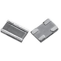
... Vishay‘s revolutionary Z-foil technology. Model VCS1625Z is a surface mount chip resistor designed with 4 pads for Kelvin connection. Utilizing Vishay’s Bulk ® Metal Z-foil as the resistance element, it provides performance capabilities far greater than other resistor technologies can supply in a product of comparable size. 0.05 ppm/° ...
Page 2
... VCS1625Z (Z-Foil) Vishay Foil Resistors FIGURE 2 - DIMENSIONS in inches (millimeters Top View INCHES L 0.250 ± 0.010 H 0.160 ± 0.010 W 0.040 maximum A 0.080 ± 0.005 B 0.040 ± 0.010 FIGURE 3 - TRIMMING TO VALUES (Conceptual Illustration) Interloop Capacitance Reduction in Series Mutual Inductance Reduction due to Opposing Current in ...
Page 3
... TCR0.2 D RESISTANCE TCR TOLERANCE Characteristic E = ± 0 ± 0 ± 1 ± 2 ± 5.0 % For any questions, contact: foil@vishaypg.com VCS1625Z (Z-Foil) Vishay Foil Resistors (1) CHARACTERISTICS 0 = standard part, tin/lead termination 9 = standard part, lead (Pb)-free termination 129 = standard part, gold plated Other = custom PACKAGING R = tape and reel ...
Page 4
... Customers using or selling Vishay Precision Group products not expressly indicated for use in such applications do so entirely at their own risk and agree to fully indemnify Vishay Precision Group for any damages arising or resulting from such use or sale. Please contact authorized Vishay Precision Group personnel to obtain written terms and conditions regarding products designed for such applications ...