GQM1885C2A2R7BB01D Murata, GQM1885C2A2R7BB01D Datasheet - Page 26
GQM1885C2A2R7BB01D
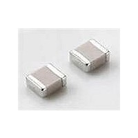
Manufacturer Part Number
GQM1885C2A2R7BB01D
Description
Multilayer Ceramic Capacitors (MLCC) - SMD/SMT 0603 2.7pF 100volts C0G +/-0.1pF
Manufacturer
Murata
Series
GQMr
Datasheet
1.GQM1885C2A3R9BB01D.pdf
(30 pages)
Specifications of GQM1885C2A2R7BB01D
Voltage Rating
100 Volts
Operating Temperature Range
- 55 C to + 125 C
Temperature Coefficient / Code
C0G (NP0)
Product
Low ESR MLCCs
Dimensions
0.8 mm W x 1.6 mm L x 0.8 mm H
Termination Style
SMD/SMT
Capacitance
2.7 pF
Tolerance
0.1 pF
Package / Case
0603 (1608 metric)
Capacitance Tolerance
± 0.1pF
Capacitor Dielectric Type
Ceramic Multi-Layer
Capacitor Case Style
0603
No. Of Pins
2
Lead Spacing
0.5mm
Operating Temperature
RoHS Compliant
Svhc
No SVHC (15-Dec-2010)
Rohs Compliant
Yes
Lead Free Status / RoHS Status
Lead free / RoHS Compliant
Available stocks
Company
Part Number
Manufacturer
Quantity
Price
Company:

Part Number:
GQM1885C2A2R7BB01D
Manufacturer:
MURATA
Quantity:
640 000


Note
• This PDF catalog is downloaded from the website of Murata Manufacturing co., ltd. Therefore, it’s specifications are subject to change or our products in it may be discontinued without advance notice. Please check with our
• This PDF catalog has only typical specifications because there is no space for detailed specifications. Therefore, please approve our product specifications or transact the approval sheet for product specifications before ordering.
sales representatives or product engineers before ordering.
C-29-C
Application Specific Capacitors
High Frequency Ceramic Capacitors – GQM Series
GQM Soldering and Mounting
4. Leaded Component Insertion
5. Flow Soldering
4. Leaded Component Insertion
5. Flow Soldering
Table 2
Recommended Conditions
Table 2
Recommended Conditions
Note
Pb-Sn Solder: Sn-37Pb
Lead Free Solder: Sn-3.0Ag-0.5Cu
Pb-Sn Solder: Sn-37Pb
Lead Free Solder: Sn-3.0Ag-0.5Cu
Peak Temperature
Peak Temperature
If the PCB is flexed when leaded components (such as
transformers and ICs) are being mounted, chips may
crack and solder joints may break.
Before mounting leaded components, support the PCB
using backup pins or special jigs to prevent warping.
When sudden heat is applied to the components, the
If the PCB is flexed when leaded components (such as
mechanical strength of the components should go down
transformers and ICs) are being mounted, chips may
because remarkable temperature change causes
crack and solder joints may break.
deformity inside components. And an excessively long
Before mounting leaded components, support the PCB
soldering time or high soldering temperature results in
using backup pins or special jigs to prevent warping.
leaching of the outer electrodes, causing poor adhesion
or a reduction in capacitance value due to loss of contact
between electrodes and end termination.
In order to prevent mechanical damage in the
When sudden heat is applied to the components, the
components, preheating shoud be required for the both
mechanical strength of the components should go down
components and the PCB board. Preheating conditions
because remarkable temperature change causes
are shown in Table 2. It is required to keep temperature
deformity inside components. And an excessively long
differential between the soldering and the components
soldering time or high soldering temperature results in
surface ( T) as small as possible.
leaching of the outer electrodes, causing poor adhesion
When components are immersed in solvent after
or a reduction in capacitance value due to loss of contact
mounting, be sure to maintain the temperature difference
between electrodes and end termination.
between the component and solvent within the range
In order to prevent mechanical damage in the
shown in Table 2.
components, preheating shoud be required for the both
Do not apply flow soldering to chips not listed in Table 2.
components and the PCB board. Preheating conditions
are shown in Table 2. It is required to keep temperature
differential between the soldering and the components
surface ( T) as small as possible.
When components are immersed in solvent after
mounting, be sure to maintain the temperature difference
between the component and solvent within the range
shown in Table 2.
Do not apply flow soldering to chips not listed in Table 2.
Optimum Solder Amount for Flow Soldering
The top of the solder fillet should be lower than the
thickness of components. If the solder amount is
excessively big, the risk of cracking is higher during
board bending or under any other stressful conditions.
Optimum Solder Amount for Flow Soldering
The top of the solder fillet should be lower than the
thickness of components. If the solder amount is
excessively big, the risk of cracking is higher during
board bending or under any other stressful conditions.
Continued from the preceding page.
Continued from the preceding page.
Atmosphere
Atmosphere
• Please read rating and
• This catalog has only typical specifications because there is no space for detailed specifications. Therefore, please approve our product specifications or transact the approval sheet for product specifications before ordering.
GRM18/21/31
LLL21/31
ERB18/21
GQM18/21
GRM18/21/31
LLL21/31
ERB18/21
GQM18/21
Part Number
Part Number
GQM18/21
CAUTION (for storage, operating, rating, soldering, mounting and handling) in this catalog to prevent smoking and/or burning, etc.
Pb-Sn Solder
Pb-Sn Solder
240-250 C
240-250 C
w
Air
Air
w
w
Temperature Differential
Temperature Differential
w
w
T 150
T 150
Lead Free Solder
Lead Free Solder
.
w
250-260 C
250-260 C
m
.
N
N
2
2
u
m
r
u
a
r
t
a
a
t
Standard Conditions for Flow Soldering
Peak Temperature
Standard Conditions for Flow Soldering
Peak Temperature
Allowable Soldering Temperature and Time
Allowable Soldering Temperature and Time
.
Temperature ( )
Temperature ( )
a
c
.
In case of repeated soldering, the accumulated
soldering time must be within the range shown above.
In case of repeated soldering, the accumulated
soldering time must be within the range shown above.
280
270
260
250
240
230
220
280
270
260
250
240
230
220
o
170 C
150 C
130 C
170 C
150 C
130 C
0
0
c
m
o
Adhesive
Adhesive
T
T
m
10
10
60-120 seconds
60-120 seconds
Preheating
Preheating
20
20
Continued on the following page.
Continued on the following page.
Soldering
Soldering
5 seconds max.
5 seconds max.
Innovator in Electronics – 45
Soldering Time (sec.)
Soldering Time (sec.)
30
30
Up to Chip Thickness
Up to Chip Thickness
Gradual
Cooling
Gradual
Cooling
Caution
Time
Time
40
40
C02E.pdf
85
85
07.2.6
13
13
Related parts for GQM1885C2A2R7BB01D
Image
Part Number
Description
Manufacturer
Datasheet
Request
R

Part Number:
Description:
Murata Microblower 20x20 DCDC Driver Board - Samples Only
Manufacturer:
Murata
Part Number:
Description:
357-036-542-201 CARDEDGE 36POS DL .156 BLK LOPRO
Manufacturer:
Murata
Datasheet:
Part Number:
Description:
Manufacturer:
Murata
Datasheet:
Part Number:
Description:
Manufacturer:
Murata
Datasheet:
Part Number:
Description:
Manufacturer:
Murata
Datasheet:
Part Number:
Description:
Manufacturer:
Murata
Datasheet:
Part Number:
Description:
Manufacturer:
Murata
Datasheet:
Part Number:
Description:
Manufacturer:
Murata
Datasheet:
Part Number:
Description:
Manufacturer:
Murata
Datasheet:
Part Number:
Description:
BLM21BD751SN1On-Board Type (DC) EMI Suppression Filters
Manufacturer:
Murata
Datasheet:
Part Number:
Description:
BLM15AG100SN1On-Board Type (DC) EMI Suppression Filters
Manufacturer:
Murata
Datasheet:
Part Number:
Description:
NFE31PT222Z1E9On-Board Type (DC) EMI Suppression Filters
Manufacturer:
Murata
Datasheet:
Part Number:
Description:
Chip Coil
Manufacturer:
Murata
Datasheet:
Part Number:
Description:
Chip Coil
Manufacturer:
Murata
Datasheet: