GRM42A7U3F820JW31L Murata, GRM42A7U3F820JW31L Datasheet - Page 211
GRM42A7U3F820JW31L
Manufacturer Part Number
GRM42A7U3F820JW31L
Description
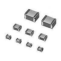
Multilayer Ceramic Capacitors (MLCC) - SMD/SMT 1808 82pF 3.15KV U2J 5%
Manufacturer
Murata
Series
GRMr
Datasheet
1.GNM1M2R61A105ME14D.pdf
(221 pages)
Specifications of GRM42A7U3F820JW31L
Voltage Rating
3.15 KVolts
Operating Temperature Range
- 55 C to + 125 C
Temperature Coefficient / Code
U2J
Product
General Type MLCCs
Dimensions
2 mm W x 4.5 mm L x 1 mm H
Termination Style
SMD/SMT
Capacitance
82 pF
Tolerance
5 %
Package / Case
1808 (4520 metric)
Lead Free Status / RoHS Status
Lead free / RoHS Compliant
Available stocks
Company
Part Number
Manufacturer
Quantity
Price
Company:

Part Number:
GRM42A7U3F820JW31L
Manufacturer:
MURATA
Quantity:
640 000


!Note
• This PDF catalog is downloaded from the website of Murata Manufacturing co., ltd. Therefore, it’s specifications are subject to change or our products in it may be discontinued without advance notice. Please check with our
• This PDF catalog has only typical specifications because there is no space for detailed specifications. Therefore, please approve our product specifications or transact the approval sheet for product specifications before ordering.
sales representatives or product engineers before ordering.
!Note
1. Vibration and Impact
3. Land Layout for Cropping PC Board
210
!Caution
[Component Direction]
Caution (Soldering and Mounting)
Do not expose a capacitor to excessive shock or vibration
during use.
Choose a mounting position that minimizes the stress imposed on the chip during flexing or bending of the board.
<Example
to be avoided>
• Please read rating and !CAUTION (for storage, operating, rating, soldering, mounting and handling) in this catalog to prevent smoking and/or burning, etc.
• This catalog has only typical specifications because there is no space for detailed specifications. Therefore, please approve our product specifications or transact the approval sheet for product specifications before ordering.
<Example
of improvement>
Locate chip
horizontal to the
direction in which
stress acts.
2. Circuit Board Material
[Chip Mounting Close to Board Separation Point]
It is possible for the chip to crack by the expansion and
shrinkage of a metal board.
Please contact us if you want to use our ceramic
capacitors on a metal board such as Aluminum.
Perforation
A
Slit
B
D
C
Continued on the following page.
Chip arrangement
Worst AGCGB~D Best
C02E.pdf
10.12.20
Related parts for GRM42A7U3F820JW31L
Image
Part Number
Description
Manufacturer
Datasheet
Request
R

Part Number:
Description:
Murata Microblower 20x20 DCDC Driver Board - Samples Only
Manufacturer:
Murata
Part Number:
Description:
357-036-542-201 CARDEDGE 36POS DL .156 BLK LOPRO
Manufacturer:
Murata
Datasheet:
Part Number:
Description:
Manufacturer:
Murata
Datasheet:
Part Number:
Description:
Manufacturer:
Murata
Datasheet:
Part Number:
Description:
Manufacturer:
Murata
Datasheet:
Part Number:
Description:
Manufacturer:
Murata
Datasheet:
Part Number:
Description:
Manufacturer:
Murata
Datasheet:
Part Number:
Description:
Manufacturer:
Murata
Datasheet:
Part Number:
Description:
Manufacturer:
Murata
Datasheet:
Part Number:
Description:
BLM21BD751SN1On-Board Type (DC) EMI Suppression Filters
Manufacturer:
Murata
Datasheet:
Part Number:
Description:
BLM15AG100SN1On-Board Type (DC) EMI Suppression Filters
Manufacturer:
Murata
Datasheet:
Part Number:
Description:
NFE31PT222Z1E9On-Board Type (DC) EMI Suppression Filters
Manufacturer:
Murata
Datasheet:
Part Number:
Description:
Chip Coil
Manufacturer:
Murata
Datasheet:
Part Number:
Description:
Chip Coil
Manufacturer:
Murata
Datasheet: