GCM188R71H103KA37D Murata, GCM188R71H103KA37D Datasheet - Page 30
GCM188R71H103KA37D
Manufacturer Part Number
GCM188R71H103KA37D
Description
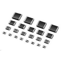
Multilayer Ceramic Capacitors (MLCC) - SMD/SMT 0603 0.01uF 50volts X7R 10%
Manufacturer
Murata
Series
GCMr
Datasheets
1.GCM188R71C105KA64D.pdf
(50 pages)
2.GCM188R71H103KA37D.pdf
(1 pages)
3.GCM155R71C104KA55D.pdf
(2 pages)
Specifications of GCM188R71H103KA37D
Voltage Rating
50 Volts
Operating Temperature Range
- 55 C to + 125 C
Temperature Coefficient / Code
X7R
Product
Automotive MLCCs
Dimensions
0.8 mm W x 1.6 mm L x 0.8 mm H
Termination Style
SMD/SMT
Capacitance
0.01 uF
Tolerance
10 %
Package / Case
0603 (1608 metric)
Lead Free Status / RoHS Status
Lead free / RoHS Compliant
Available stocks
Company
Part Number
Manufacturer
Quantity
Price
Company:

Part Number:
GCM188R71H103KA37D
Manufacturer:
MURATA
Quantity:
640 000
Company:
Part Number:
GCM188R71H103KA37D
Manufacturer:
MURATA
Quantity:
32 000
Part Number:
GCM188R71H103KA37D 0603 X7R 103K 50V
Manufacturer:
MURATA/村田
Quantity:
20 000


1
!Note
• This PDF catalog is downloaded from the website of Murata Manufacturing co., ltd. Therefore, it’s specifications are subject to change or our products in it may be discontinued without advance notice. Please check with our
• This PDF catalog has only typical specifications because there is no space for detailed specifications. Therefore, please approve our product specifications or transact the approval sheet for product specifications before ordering.
sales representatives or product engineers before ordering.
!Note
4. Flux Application
5. Flow Soldering
1. Resin Coating
2. Circuit Design
28
Notice
An excessive amount of flux generates a large quantity of
Flux containing too high percentage of halide may cause
Do not use strong acidic flux.
Do not use water-soluble flux*.
(*Water-soluble flux can be defined as non rosin type flux
Set temperature and time to ensure that leaching of the
Notice (Other)
When selecting resin materials, select those with
low contraction.
GCM Series capacitors in this catalog are not safety
recognized products.
flux gas, causing deteriorated solderability.
So apply flux thinly and evenly throughout.
(A foaming system is generally used for flow soldering.)
corrosion of the outer electrodes unless sufficient
cleaning. Use flux with a halide content of 0.2% max.
including wash-type flux and non-wash-type flux.)
outer electrode does not exceed 25% of the chip end
area as a single chip (full length of the edge A-B-C-D
shown below) and 25% of the length A-B shown below as
mounted on substrate.
Continued from the preceding page.
• Please read rating and !CAUTION (for storage, operating, rating, soldering, mounting and handling) in this catalog to prevent smoking and/or burning, etc.
• This catalog has only typical specifications because there is no space for detailed specifications. Therefore, please approve our product specifications or transact the approval sheet for product specifications before ordering.
3. Remarks
The above notices are for standard applications and
conditions. Contact us when the products are used
in special mounting conditions. Select optimum
conditions for operation as they determine the
reliability of the product after assembly.
The data herein are given in typical values, not
guaranteed ratings.
[As a Single Chip]
[As Mounted on Substrate]
B
C
B
A
A
D
Outer Electrode
C03E.pdf
09.3.31
Related parts for GCM188R71H103KA37D
Image
Part Number
Description
Manufacturer
Datasheet
Request
R

Part Number:
Description:
Murata Microblower 20x20 DCDC Driver Board - Samples Only
Manufacturer:
Murata
Part Number:
Description:
357-036-542-201 CARDEDGE 36POS DL .156 BLK LOPRO
Manufacturer:
Murata
Datasheet:
Part Number:
Description:
Manufacturer:
Murata
Datasheet:
Part Number:
Description:
Manufacturer:
Murata
Datasheet:
Part Number:
Description:
Manufacturer:
Murata
Datasheet:
Part Number:
Description:
Manufacturer:
Murata
Datasheet:
Part Number:
Description:
Manufacturer:
Murata
Datasheet:
Part Number:
Description:
Manufacturer:
Murata
Datasheet:
Part Number:
Description:
Manufacturer:
Murata
Datasheet:
Part Number:
Description:
BLM21BD751SN1On-Board Type (DC) EMI Suppression Filters
Manufacturer:
Murata
Datasheet:
Part Number:
Description:
BLM15AG100SN1On-Board Type (DC) EMI Suppression Filters
Manufacturer:
Murata
Datasheet:
Part Number:
Description:
NFE31PT222Z1E9On-Board Type (DC) EMI Suppression Filters
Manufacturer:
Murata
Datasheet:
Part Number:
Description:
Chip Coil
Manufacturer:
Murata
Datasheet:
Part Number:
Description:
Chip Coil
Manufacturer:
Murata
Datasheet: