Y078510K0000T9L Vishay, Y078510K0000T9L Datasheet - Page 3
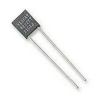
Y078510K0000T9L
Manufacturer Part Number
Y078510K0000T9L
Description
RES 10K OHM 1W .01% FOIL RAD
Manufacturer
Vishay
Series
Sr
Datasheet
1.Y000710R0000A9L.pdf
(6 pages)
Specifications of Y078510K0000T9L
Temperature Coefficient
±1ppm/°C
Resistance (ohms)
10K
Number Of Terminations
2
Package / Case
Radial
Power (watts)
0.6W
Composition
Metal Foil
Features
Non-Inductive
Tolerance
±0.01%
Size / Dimension
0.300" L x 0.105" W (7.62mm x 2.67mm)
Height
0.336" (8.53mm)
Resistance
10kohm
Resistance Tolerance
± 0.01%
Power Rating
600mW
Voltage Rating
300V
Resistor Element Material
Metal Foil
Resistor Case Style
Radial
Lead Free Status / RoHS Status
Lead free / RoHS Compliant
Other names
S102JT 10K0000 0.01%
Y0785-10KA
Y0785-10KA


Document Number: 63001
Revision: 17-May-10
FIGURE 3 - POWER DERATING CURVE
TABLE 3 - ENVIRONMENTAL PERFORMANCE COMPARISON
Test Group I
Thermal shock, 5 x (- 65 °C to + 150 °C)
Short time overload, 6.25 x rated power
Test Group II
Resistance temperature characteristics
Characteristic
Low temperature storage (24 h at - 65 °C)
Low temperature operation
(45 min, rated power at - 65 °C)
Terminal strength
Test Group III
DWV
Resistance to solder heat
Moisture resistance
Test Group IV
Shock
Vibration
Test Group V
Life test at 0.3 W/+ 125 °C
2000 h
10 000 h
Test Group Va
Life test at 0.6 W (2 x rated power)/+ 70 °C, 2000 h
Test Group VI
High temperature exposure (2000 h at + 175 °C)
Test Group VII
Voltage coefficient
200 %
175 %
150 %
125 %
100 %
75 %
50 %
25 %
0 %
- 75
- 55 °C
- 50
- 25
Ambient Temperature (°C)
0
25
50
+ 70 °C
75
Double Rated Power
100
125
Rated Power
150
For any questions, contact:
Safe operation
for < 150 ppm
ΔR after 2000 h
load-life.
Δ
175
200
MIL-PRF-55182
± 25 ppm/°C
± 0.15 %
± 0.15 %
± 0.15 %
5 ppm/V
CHAR J
± 0.2 %
± 0.2 %
± 0.2 %
± 0.1 %
± 0.4 %
± 0.2 %
± 0.2 %
± 0.5 %
± 2.0 %
± 0.5 %
± 2.0 %
foil@vishaypg.com
FIGURE 4 - TRIMMING TO VALUES
Interloop Capacitance
Reduction in Series
Mutual Inductance
Reduction due
to Change in
Current Direction
± 0.015 % (150 ppm)
± 0.015 % (150 ppm)
± 0.01 % (100 ppm)
± 0.01 % (100 ppm)
± 0.01 % (100 ppm)
± 0.01 % (100 ppm)
± 0.01 % (100 ppm)
± 0.01 % (100 ppm)
± 0.01 % (100 ppm)
± 0.05 % (500 ppm)
± 0.01 % (100 ppm)
± 0.01 % (100 ppm)
± 0.05 % (500 ppm)
± 0.1 % (1000 ppm)
MAXIMUM ΔR
± 4.5 ppm/°C
< 0.1 ppm/V
(conceptual illustration)
S-SERIES
Note: Foil shown in black, etched spaces in white
Vishay Foil Resistors
After Trimming
Current Path
± 0.002 % (20 ppm)
± 0.003 % (30 ppm)
± 0.002 % (20 ppm)
± 0.002 % (20 ppm)
± 0.002 % (20 ppm)
± 0.002 % (20 ppm)
± 0.005 % (50 ppm)
± 0.01 % (100 ppm)
± 0.002 % (20 ppm)
± 0.002 % (20 ppm)
± 0.01 % (100 ppm)
± 0.03 % (300 ppm)
± 0.01 % (100 ppm)
± 0.05 % (500 ppm)
www.foilresistors.com
from Shorting Strip Area
± 2.0 ppm/°C
TYPICAL ΔR
Changing Current Path
< 0.1 ppm/V
Removes this Material
S-SERIES
Trimming Process
S Series
and Increasing
Resistance
Before Trimming
Current Path
3
Related parts for Y078510K0000T9L
Image
Part Number
Description
Manufacturer
Datasheet
Request
R

Part Number:
Description:
357-036-542-201 CARDEDGE 36POS DL .156 BLK LOPRO
Manufacturer:
Vishay
Datasheet:
Part Number:
Description:
357-036-542-201 CARDEDGE 36POS DL .156 BLK LOPRO
Manufacturer:
Vishay
Datasheet:
Part Number:
Description:
357-036-542-201 CARDEDGE 36POS DL .156 BLK LOPRO
Manufacturer:
Vishay
Datasheet:
Part Number:
Description:
357-036-542-201 CARDEDGE 36POS DL .156 BLK LOPRO
Manufacturer:
Vishay
Datasheet:
Part Number:
Description:
357-036-542-201 CARDEDGE 36POS DL .156 BLK LOPRO
Manufacturer:
Vishay
Datasheet:
Part Number:
Description:
357-036-542-201 CARDEDGE 36POS DL .156 BLK LOPRO
Manufacturer:
Vishay
Datasheet:
Part Number:
Description:
357-036-542-201 CARDEDGE 36POS DL .156 BLK LOPRO
Manufacturer:
Vishay
Datasheet:
Part Number:
Description:
357-036-542-201 CARDEDGE 36POS DL .156 BLK LOPRO
Manufacturer:
Vishay
Datasheet:
Part Number:
Description:
357-036-542-201 CARDEDGE 36POS DL .156 BLK LOPRO
Manufacturer:
Vishay
Datasheet:
Part Number:
Description:
357-036-542-201 CARDEDGE 36POS DL .156 BLK LOPRO
Manufacturer:
Vishay
Datasheet:
Part Number:
Description:
357-036-542-201 CARDEDGE 36POS DL .156 BLK LOPRO
Manufacturer:
Vishay
Datasheet:
Part Number:
Description:
357-036-542-201 CARDEDGE 36POS DL .156 BLK LOPRO
Manufacturer:
Vishay
Datasheet:
Part Number:
Description:
357-036-542-201 CARDEDGE 36POS DL .156 BLK LOPRO
Manufacturer:
Vishay
Datasheet:
Part Number:
Description:
357-036-542-201 CARDEDGE 36POS DL .156 BLK LOPRO
Manufacturer:
Vishay
Datasheet:
Part Number:
Description:
357-036-542-201 CARDEDGE 36POS DL .156 BLK LOPRO
Manufacturer:
Vishay
Datasheet: