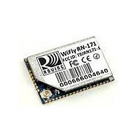
RN-174 Roving Networks Inc, RN-174 Datasheet - Page 8

RN-174
Manufacturer Part Number
RN-174
Description
RF EVAL GSX SUPER MODULE
Manufacturer
Roving Networks Inc
Type
Transceiver, 802.11 b/gr
Specifications of RN-174
Frequency
2.402GHz ~ 2.48GHz
Wireless Frequency
2402 MHz to 2480 MHz
Interface Type
RS-232, SPI, UART
Modulation
DSSS, OFDM
Security
128 bit WEP, AES, TKIP
Operating Voltage
3.3 V
Output Power
12 dBm
Operating Temperature Range
- 40 C to + 85 C
Board Size
1950 mm x 1105 mm
Antenna
Supports Chip, PCB Trace, Wire, U.FL Connector for External
For Use With/related Products
RN-171
Lead Free Status / RoHS Status
Lead free / RoHS Compliant
Lead Free Status / RoHS Status
Lead free / RoHS Compliant, Lead free / RoHS Compliant
Other names
740-1040
RN-171 Data Sheet
www.rovingnetworks.com
RN-171-DS v1.0 1/24/2011
Design Concerns
Antenna Design. A recommended PCB trace Antenna pattern is shown below. The antenna ground should be
connected with at least 2 vias to the ground plane and / or ground polygon on both top and bottom layers.
The ground plane should come close to the antenna, exactly where shown in the diagram. The distance is critical.
There should be no ground place / trace under the antenna, under any circumstance.
The antenna feed will go through the polygon on a 50 ohm impedance trace to the source of the signal.
Unless the antenna trace is exactly 50 ohm and the source has a 50 ohm output impedance a matching PI filter
should be used (2 capacitors and an inductor).
The left side of the antenna should be placed on the PCB edge. If not possible please leave at least 1 inch of
clearance from any trace or ground plane. The top and bottom of the antenna (the shorter side) should either be
placed on the PCB edge or have at least 1 inch clearance from any trace or ground plane.
To control the impedance of the antenna feed the board should be a 4 layer board with a dedicated ground plane and
a thickness of around 8-14 mil between the ground plane and the top layer (where the antenna feed is routed).
A two layer board would not be thin enough to obtain the desired impedance using a decent width for the trace.
Antenna feed
Antenna Ground
Using Batteries The RN-171 module does not have a Boost Regulator circuit. This makes the choice of batteries
absolutely critical because if the battery voltage drops below 3V, the module performance will start to degrade.. One
possible battery of choice is the ER14505 3.6V battery. This battery is known to have a long battery life. If this battery
is used to power the module, it is recommended that you use a 1000uF to 3000uF bypass capacitor as the ER14505
battery has high output impedance.
Boost Regulator: The RN-171 does not have a boost regulator on board. A recommended circuit for the boost
regulator is shown below.
809 University Avenue
•
Los Gatos, CA 95032
•
Tel (408) 395-6539
• info@RovingNetworks.com
~
p age
8
~


