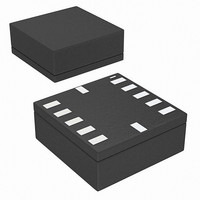
BMA020 Bosch Sensortec, BMA020 Datasheet - Page 23

BMA020
Manufacturer Part Number
BMA020
Description
3-AXIS ACCELEROMETER DIGITAL I/F
Manufacturer
Bosch Sensortec
Datasheet
1.BMA020.pdf
(50 pages)
Specifications of BMA020
Axis
X, Y, Z
Acceleration Range
± 2g, 4g, 8g
Sensitivity
256LSB/g, 128LSB/g, 64LSB/g
Voltage - Supply
2 V ~ 3.6 V
Output Type
Digital
Bandwidth
3kHz
Interface
I²C, SPI
Mounting Type
Surface Mount
Package / Case
12-LGA
For Use With
828-1014 - BMA020 TRIBOX DEMO BOARD W/USB828-1008 - BMA020 DAUGHTERCARD FOR DEV KIT
Lead Free Status / RoHS Status
Lead free / RoHS Compliant
Other names
828-1000-2
Available stocks
Company
Part Number
Manufacturer
Quantity
Price
Part Number:
BMA020
Manufacturer:
BOSCH/博世
Quantity:
20 000
Data sheet
BMA020
Bosch Sensortec
Digital, triaxial acceleration sensor
4. Digital interface
BMA020 is capable to be adjusted to customer’s specific hardware requirements. It provides
three different digital interfaces (SPI 4-wire, SPI 3-wire, I²C) and an interrupt output pin.
The digital interface is used for regular reading of data registers (acceleration). For a complete
read out of acceleration data two successive read cycles are required. The 10 bit coded data
word is split into 8 MSB and 2 LSB. The most significant bit (MSB) is transferred first during
address and data phases.
The serial interface is also used for verifying status registers or writing to control registers.
4.1 SPI
The SPI interfaces using three wire or four wire bus provide 16-bit protocols. Multiple read out is
possible.
The communication is opened with a read/write control bit (R/W=0 for writing, R/W=1 for
reading) followed by 7 address bits and at least 8 data bits (see figure 6 and figure 7). For a
complete readout of 10 bit acceleration data from all axes the sensor IC provides the option to
use an automatic incremented read command to read more than one byte (multiple read). This
is activated when the serial enable pin CSB (chip select) stays active low after the read out of a
data register. Thus, read out of data LSB will also cause read out of MSB if the CSB stays low
for further 8 cycles of system clock.
The customer has the possibility to communicate with operational registers at addresses 00h-
15h via SPI interface (chip identification Bytes, data Bytes, status and control registers with
setting parameters). Access to the residual part of the memory map is locked (section 3.3.3). If
the master addresses outside the range 00h-15h then SDI will go to tri-state enabling the
communication of a second device on the same CSB and SDI line.
The CSB input has an internal 120kΩ pull-up resistor to V
.
DDIO
4.1.1 Four-wire SPI interface
The 4-wire SPI is the default serial interface. The customer can easily activate the 3-wire SPI by
writing a control bit (SPI4=0). The 4-wire SPI interface uses SCK (serial clock), CSB (chip
select), SDI (serial data in) and SDO (serial data out).
CSB is active low. Data on SDI is latched by BMA020 at SCK rising edge and SDO is changed
at SCK falling edge (SPI mode 3). Communication starts when CSB goes to low and stops
when CSB goes to high; during these transitions on CSB, SCK must be high. While CSB=1, no
SDI change is allowed when SCK=1.
Rev. 1.2
Page 23
30 May 2008
© Bosch Sensortec GmbH reserves all rights even in the event of industrial property rights. We reserve all rights of disposal such
as copying and passing on to third parties. BOSCH and the symbol are registered trademarks of Robert Bosch GmbH, Germany.
Note: Specifications within this document are subject to change without notice.


