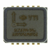
SCA3100-D04 VTI Technologies, SCA3100-D04 Datasheet - Page 10

SCA3100-D04
Manufacturer Part Number
SCA3100-D04
Description
ACCELEROMETER 3-AXIS +/-2G SPI
Manufacturer
VTI Technologies
Specifications of SCA3100-D04
Axis
X, Y, Z
Acceleration Range
±2g
Sensitivity
900 counts/g
Voltage - Supply
3 V ~ 3.6 V
Output Type
Digital
Bandwidth
55Hz
Interface
SPI
Mounting Type
Surface Mount
Package / Case
12-SMD
For Use With
551-1061 - EVAL BOARD ACCELEROMETER 3-AXIS551-1056 - KIT DEMO ACCELEROMETER SCA3100
Lead Free Status / RoHS Status
Lead free / RoHS Compliant
Other names
551-1055-2
2.3.2
2.3.3
VTI Technologies Oy
www.vti.fi
Usage
Examples
The absolute value of programmable Threshold Level (TL) is 0 < |TL| < FS g (FS is sensor full
scale measuring range). NOTE: Due to power consumption optimization, the step size between
each step and axis is not the same, see section 3.4 for threshold level details.
The triggering condition can be defined using OR/AND logic:
1. Any sensing direction can be configured to trigger the interrupt (OR condition).
2. Any sensing direction can be configured to be required to trigger the interrupt (AND condition).
Figure 3. Motion detector operation.
The MD mode can be enabled by setting the MODE bits in the MODE register to "011". The trigger
condition can be defined by setting REQ_Z, REQ_Y, REQ_X, EN_Z, EN_Y and EN_X bits in
MD_CTRL register and Z_TH, Y_TH and Z_TH bits in MD_Z_TH, MD_Y_TH and MD_X_TH
registers, respectively. See section 3.4 for the configuration register and section 2.7 for the
interrupt functionality details.
In MD mode, acceleration data is not available in registers X_LSB, X_MSB, Y_LSB, Y_MSB,
Z_LSB, Z_MSB and BUF_DATA.
A simple example of motion detection usage:
In the next example, the motion detector is configured to give an interrupt on motion only in the X-
OR Y-axis direction:
Acceleration
X, Y or Z
INT output
1. Write "00000011" (03h) into the MODE register (enable motion detection mode,
2. Acceleration data is not available when the SCA3000 is in motion detection mode.
3. The INT-pin is activated when motion is detected, see section 2.7 for detailed INT-pin
1. Write "00000011" (03h) into MODE register (enable motion detection mode,
2. Write "00000000" (00h) into UNLOCK register
3. Write "01010000" (50h) into UNLOCK register
4. Write "10100000" (A0h) into UNLOCK register
5. Write "00000010" (02h) into CTRL_SEL register (to select indirect MD_CTRL register)
6. Write "00000011" (03h) into CTRL_DATA register (this data is written into MD_CTRL
+TL
-TL
"1"
"0"
MODE_BITS = '011').
information.
MODE_BITS = '011')
register, enable trigger on Y-channel, EN_Y = '1', enable trigger on X-channel, EN_X = '1')
Acceleration exceeds
the threshold level
due to motion
T1
T1
Doc.Nr. 8257300A.07
T2
T2
T3
T3
T4
T4
T5
T5
T6
T6
T7
T7
Unlock sequence for register lock
T8
T8
Time
Time
SCA3000 Series
Rev.A.07
10/ 43


