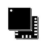
LIS33DETR STMicroelectronics, LIS33DETR Datasheet - Page 23

LIS33DETR
Manufacturer Part Number
LIS33DETR
Description
IC ACCELEROMETER 3AXIS 16LLGA
Manufacturer
STMicroelectronics
Datasheet
1.STEVAL-MKI088V1.pdf
(31 pages)
Specifications of LIS33DETR
Axis
X, Y, Z
Acceleration Range
±2.3g, 9.2g
Sensitivity
18mg/digit, 72mg/digit
Voltage - Supply
2.16 V ~ 3.6 V
Output Type
Digital
Bandwidth
100Hz ~ 400Hz Selectable
Interface
I²C, SPI
Mounting Type
Surface Mount
Package / Case
16-LGA
Package Type
LGA
Operating Supply Voltage (min)
2.16V
Operating Supply Voltage (typ)
2.5/3.3V
Operating Supply Voltage (max)
3.6V
Operating Temperature (min)
-40C
Operating Temperature (max)
85C
Operating Temperature Classification
Industrial
Product Depth (mm)
3mm
Product Length (mm)
3mm
Mounting
Surface Mount
Pin Count
16
Sensing Axis
X, Y, Z
Acceleration
2 g, 8 g
Digital Output - Number Of Bits
8 bit
Supply Voltage (max)
3.6 V
Supply Voltage (min)
2.16 V
Supply Current
0.3 mA
Maximum Operating Temperature
+ 85 C
Minimum Operating Temperature
- 40 C
Digital Output - Bus Interface
I2C, SPI
Mounting Style
SMD/SMT
Shutdown
Yes
Lead Free Status / RoHS Status
Lead free / RoHS Compliant
Available stocks
Company
Part Number
Manufacturer
Quantity
Price
Company:
Part Number:
LIS33DETR
Manufacturer:
STMicroelectronics
Quantity:
6 400
Part Number:
LIS33DETR
Manufacturer:
ST
Quantity:
20 000
LIS33DE
7
7.1
Register description
The device contains a set of registers which are used to control its behavior and to retrieve
acceleration data. The registers address, made of 7 bits, is used to identify them and to
write the data through serial interface.
CTRL_REG1 (20h)
Table 16.
Table 17.
DR bit allows to select the data rate at which acceleration samples are produced. The
default value is ‘0’ which corresponds to a data-rate of 100 Hz. By changing the content of
DR to ‘1’ the selected data-rate will be set equal to 400 Hz.
PD bit allows to turn the device out of power-down mode. The device is in power-down
mode when PD= ‘0’ (default value after boot). The device is in normal mode when PD is set
to ‘1’.
STP, STM bits are used to activate the self-test function. When the bit is set to one, an
output change will occur to the device outputs (refer to Table 2 and 3 for specification) thus
allowing to check the functionality of the whole measurement chain.
Zen bit enables the generation of Data Ready signal for Z-axis measurement channel when
set to ‘1’. The default value is ‘1’.
Yen bit enables the generation of Data Ready signal for Y-axis measurement channel when
set to ’1’. The default value is ’1’.
Xen bit enables the generation of Data Ready signal for X-axis measurement channel when
set to ’1’. The default value is ’1’.
DR
PD
FS
STP, STM
Zen
Yen
Xen
DR
CTRL_REG1 (20h) register
CTRL_REG1 (20h) register description
Self test enable. Default value: 0
Data rate selection. Default value: 0
(0: 100 Hz output data rate; 1: 400 Hz output data rate)
Power down control. Default value: 0
(0: power down mode; 1: active mode)
Full scale selection. Default value: 0
(refer to table 2 for typical full scale value)
(0: normal mode; 1: self test P, M enabled)
Z axis enable. Default value: 1
(0: Z axis disabled; 1: Z axis enabled)
Y axis enable. Default value: 1
(0: Y axis disabled; 1: Y axis enabled)
X axis enable. Default value: 1
(0: X axis disabled; 1: X axis enabled)
PD
FS
Doc ID 15596 Rev 1
STP
STM
Zen
Register description
Yen
Xen
23/31


