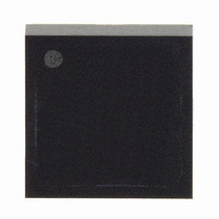
LIS3L02ALTR STMicroelectronics, LIS3L02ALTR Datasheet - Page 8

LIS3L02ALTR
Manufacturer Part Number
LIS3L02ALTR
Description
ACCELEROMETER TRPL AXIS 8-LGA
Manufacturer
STMicroelectronics
Datasheet
1.LIS3L02AL.pdf
(17 pages)
Specifications of LIS3L02ALTR
Axis
X, Y, Z
Acceleration Range
±2g
Sensitivity
Vdd/5 V/g
Voltage - Supply
2.4 V ~ 3.6 V
Output Type
Analog
Bandwidth
1.5kHz
Interface
IC
Mounting Type
Surface Mount
Package / Case
8-LGA
Sensing Axis
X, Y, Z
Acceleration
2 g
Supply Voltage (max)
3.6 V
Supply Voltage (min)
2.4 V
Supply Current
0.85 mA
Maximum Operating Temperature
+ 85 C
Minimum Operating Temperature
- 40 C
Lead Free Status / RoHS Status
Lead free / RoHS Compliant
Available stocks
Company
Part Number
Manufacturer
Quantity
Price
Mechanical and electrical specifications
8/17
Self Test allows to test the mechanical and electric part of the sensor, allowing the seismic
mass to be moved by means of an electrostatic test-force. The Self Test function is off when
the ST pin is connected to GND. When the ST pin is tied at Vdd an actuation force is applied
to the sensor, simulating a definite input acceleration. In this case the sensor outputs will
exhibit a voltage change in their DC levels which is related to the selected full scale and
depending on the Supply Voltage through the device sensitivity. When ST is activated, the
device output level is given by the algebraic sum of the signals produced by the acceleration
acting on the sensor and by the electrostatic test-force. If the output signals change within
the amplitude specified inside Table 2, than the sensor is working properly and the
parameters of the interface chip are within the defined specification.
Output impedance describes the resistor inside the output stage of each channel. This
resistor is part of a filter consisting of an external capacitor of at least 1nF and the internal
resistor. Due to the high resistor level only small, inexpensive external capacitors are
needed to generate low corner frequencies. When interfacing with an ADC it is important to
use high input impedance input circuitries to avoid measurement errors. Note that the
minimum load capacitance forms a corner frequency beyond the resonance frequency of
the sensor. For a flat frequency response a corner frequency well below the resonance
frequency is recommended. In general the smallest possible bandwidth for an particular
application should be chosen to get the best results.
LIS3L02AL


