AMT102-V KIT CUI Inc, AMT102-V KIT Datasheet - Page 3
AMT102-V KIT
Manufacturer Part Number
AMT102-V KIT
Description
ENCODER PROG 16RES SW TTL RADIAL
Manufacturer
CUI Inc
Series
AMT10Xr
Datasheet
1.AMT102-V_KIT.pdf
(8 pages)
Specifications of AMT102-V KIT
Encoder Type
Capacitive
Output Type
Quadrature with Index (Incremental)
Pulses Per Revolution
Programmable
Voltage - Supply
5VDC
Actuator Type
2mm ~ 8mm Open Center
Detent
No
Built In Switch
No
Mounting Type
Chassis Mount, Motors
Orientation
Vertical
Termination Style
Terminal Pins
Lead Free Status / RoHS Status
Lead free / RoHS Compliant
Rotational Life (cycles Min)
-
Other names
102-1307
AMT102-V
AMT102I-D016-ASLP
AMT102-V
AMT102I-D016-ASLP


SERIES:
RESOLUTION SETTINGS
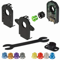
ASSEMBLY PROCEDURE
1 .
2.
3
4.
7
8
STEP 1
. Slide Shaft Adaptor over Sleeve.
STEP 4
. Fasten the Base on the motor.
. Remove Tool B.
Insert Tool A as a spacer that defi nes the distance to the mounting surface.
Slide appropriate sized Sleeve over shaft all the way down to Tool A.
Use Tool B to press Shaft Adaptor over Sleeve until fl ush with Tool A.
AMT10X
20050 SW 112
Resolution (PPR)
th
2048
1000
1024
800
384
500
400
192
512
250
200
256
125
100
Ave. Tualatin, Oregon 97062
96
48
Maximum RPM
5
6
9.
15000
15000
15000
15000
30000
30000
30000
30000
30000
30000
30000
30000
7500
7500
7500
7500
STEP 2
. Remove Tools A and B.
. Place Base on motor, with Tool B used as a centering tool.
STEP 5
Slide the Top Cover onto the Base, carefully observing that the teeth of
the Shaft Adaptor align with the grooves in the hub.
DESCRIPTION: INCREMENTAL ENCODER
4
1
1
1
1
1
1
1
1
0
0
0
0
0
0
0
0
phone 503.612.2300
3
1
1
1
1
0
0
0
0
1
1
1
1
0
0
0
0
0 = On, 1 = Off
2
1
1
0
0
1
1
0
0
1
1
0
0
1
1
0
0
1
1
0
1
0
1
0
1
0
1
0
1
0
1
0
1
0
fax 503.612.2380 www.cui.com
10
11
6a .
6b.
STEP 6
DIP switch:
Example setting: 500
STEP 3
ON
. Make sure the snaps are fully engaged and the Top Cover is fl ush
. When assembly is fi nished, the Shaft Adaptor should be about
with the Base.
fl ush with the front of the Encoder and the Motor Shaft should rotate freely.
Align Tool B with fl ange on Base.
Slide Base and Tool B onto motor, centering onto the Shaft Adapter.
(on)
0
1
(off)
date
page
4
3
2
1
11/2010
3 of 8
Align Tool B with
fl ange on Base
Related parts for AMT102-V KIT
Image
Part Number
Description
Manufacturer
Datasheet
Request
R

Part Number:
Description:
AMT10 POS BOTH SIDE INS CN 750-250
Manufacturer:
THOMAS & BETTS

Part Number:
Description:
CABLE ASSY LATCH 5PIN 5X22AWG 1'
Manufacturer:
CUI Inc
Datasheet:

Part Number:
Description:
CABLE ASSY LATCH 5PIN 5X22AWG 1'
Manufacturer:
CUI Inc
Datasheet:

Part Number:
Description:
CABLE SHLD LATCH 5PIN 24AWG 6'
Manufacturer:
CUI Inc
Datasheet:

Part Number:
Description:
LINE DRIVER CABLE FOR AMT-102 1M
Manufacturer:
CUI Inc
Datasheet:

Part Number:
Description:
LINE DRIVER CABLE FOR AMT-103 1M
Manufacturer:
CUI Inc
Datasheet:

Part Number:
Description:
CABLE SHLD MATING 5PIN 24AWG 6'
Manufacturer:
CUI Inc
Datasheet:

Part Number:
Description:
CABLE ASSY LATCH 5PIN 5X24AWG 6'
Manufacturer:
CUI Inc
Datasheet:


Part Number:
Description:
SPEAKER ALNICO 8OHM 2W 100MM SQR
Manufacturer:
CUI Inc
Datasheet:
Part Number:
Description:
SPEAKER ALNICO 8OHM 2W 100MM SQR
Manufacturer:
CUI Inc
Datasheet:

Part Number:
Description:
ac-dc converter
Manufacturer:
CUI [CUI INC]
Datasheet:
Part Number:
Description:
MEDICAL SWITCHING POWER SUPPLY
Manufacturer:
CUI [CUI INC]
Datasheet:
Part Number:
Description:
DC-DC Converter
Manufacturer:
CUI [CUI INC]
Datasheet:
Part Number:
Description:
DC/DC Converter
Manufacturer:
CUI [CUI INC]
Datasheet: