5301 3M, 5301 Datasheet - Page 2
5301
Manufacturer Part Number
5301
Description
Motor Splice Kit
Manufacturer
3M
Series
5300r
Datasheet
1.5301.pdf
(4 pages)
Specifications of 5301
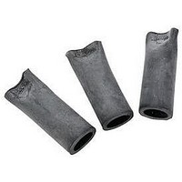
Kit Contents
3 Splices, 3 Lug Covers, 3 Tubes Silicone Grease, 3 Mastic Sealing Strips
Wire Size (awg)
12-5
Insulator Material
EPDM Rubber
Accessory Type
Motor Splice Kit
Insulator Color
Black
Rohs Compliant
Yes
For Use With
Motor Leads Terminated With Compression Lugs
Lead Free Status / RoHS Status
Lead free / RoHS Compliant
Available stocks
Company
Part Number
Manufacturer
Quantity
Price
Company:

Part Number:
530102B00150G
Manufacturer:
ATH
Quantity:
1 708
Part Number:
53014
Manufacturer:
TI/德州仪器
Quantity:
20 000
Company:
Part Number:
53014-0200
Manufacturer:
MOLEX
Quantity:
55 596
Company:
Part Number:
53014-0210
Manufacturer:
FUJITSU
Quantity:
1 300
Company:
Part Number:
53014-0210
Manufacturer:
MOLEX
Quantity:
49 579
Company:
Part Number:
53014-0210
Manufacturer:
MOLEX
Quantity:
35 000
Part Number:
53014-0410
Manufacturer:
MOLEX
Quantity:
20 000


A. Prepare Cables According to Standard
1. Check to be sure cable sizes fit within the kit range as
2. Remove cable insulation for length recommended
Note:
For Jacketed Feeder Cable Only:
If jacketed feeder cable is used, remove an additional
1/4" (6 mm) of jacket, leaving 1/4" (6 mm) of cable
insulation exposed (Figure 2).
Jacket
Procedures
shown in Table 1.
by terminal lug manufacturer; if no information is
available, remove for depth of lug barrel.
If a split bolt connector is used, refer to Table 2
below for maximum split bolt size for each kit.
Kit No.
5300
5301
Figure 1
Figure 2
"
Table 2
Max. Split
Bolt Size
10 AWG
8 AWG
Insulation
2
B. Install Lugs
1. Install and crimp lugs per manufacturer’s direction.
2. Clean insulation (or jacket as applicable) for
3. Bolt lugs together. See Table 1 for maximum bolt
C. Installation
Note:
1. To gauge mastic build up in next step, temporarily
2. Separate the cables and apply mastic strip around
For Jacketed Feeder Cable Only:
For jacketed feeder cable, center mastic strip over cut-
back edge of cable jacket, so that it seals onto both the
cable jacket and insulation (Figure 4).
(See back page if 3M lugs are used.)
approximately 6" (152 mm).
length, and Figure 1 for proper bolt/lug arrangement.
install lug cover over bolted lugs, leaving 1/2" (13
mm) of lug exposed.
insulation and between them at a position just onto
insulation (Figure 3). For jacketed feeder cable, see
note below. Build thickness so the overall diameter is
slightly larger than the observed inside diameter of the
lug cover. Press cables together and be sure that no
void exists between them.
MASTIC STRIP OVERWRAPPED WITH
VINYL TAPE
JACKET EDGE
If moisture resistance is not required, proceed
to Step 4.
Figure 3
Figure 4
MASTIC STRIP OVERWRAPPED WITH
VINYL TAPE
APPLY SILICONE GREASE
APPLY SILICONE GREASE
INSULATION
LUG COVER
LUG COVER
78-8126-0998-6-A