224928-1 Tyco Electronics, 224928-1 Datasheet - Page 2
224928-1
Manufacturer Part Number
224928-1
Description
PROCRIMP HT&D MOD PLUG ESR
Manufacturer
Tyco Electronics
Series
Pro-Crimper™ IIIr
Type
Crimp Tool Assemblyr
Specifications of 224928-1
Rohs Compliant
NA
Tool Type
Hand Crimper
Features
Side Entry, Ratchet
Product
Crimping, Stripping & Cutting Tools & Drills
Description/function
Hand crimp tool assembly
Lead Free Status / RoHS Status
Not applicable / Not applicable
For Use With/related Products
Modular Strain Relief
For Use With
558527-3 - STRAIN RELIEF EXT MOD PLUGA9130 - CONN STRAIN RELIEF MODULAR TIN
Lead Free Status / Rohs Status
Lead free / RoHS Compliant
Other names
A9800


3. INSTALLATION AND REMOVAL OF
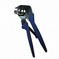
2
PRO-CRIMPER III Hand Tool Assembly 224928-1 with Die Assembly 224928-2
of 4
DIE ASSEMBLY
1. Open the tool handles and remove the two die
retaining screws from the tool jaws.
2. Place the anvil die so that the chamfered side
faces outward when mounted in the moving jaw of
the tool frame.
3. Insert the two die retaining pins.
4. Insert the die retaining screw through the jaw
and through the anvil die, and tighten the screw
just enough to hold the die in place. Do not tighten
the screw completely at this time.
5. Observe the wire insulation diameter markings
on the indenter die. Place the indenter die so that
the crimping chamber to be used is facing outward
when mounted in the stationary jaw of the tool
frame.
6. Insert the two die retaining pins.
7. Insert the die retaining screw through the jaw
and the indenter die, and tighten the screw just
enough to hold the die in place. Do not tighten the
screw completely at this time.
8. Carefully close the tool handles, making sure
that the anvil and indenter align properly. Continue
closing the tool handles until the ratchet in the tool
frame has engaged sufficiently to hold the anvil
Indenter
Die
Anvil
Die
Wire Insulation
Diameter Markings
(Figure 2)
Chamfer
Tyco Electronics Corporation
Figure 2
4. CRIMPING PROCEDURE
Assemble the modular plug connector according to
Application Specification 114–6016. Insert the
external strain relief into the modular plug as shown in
Figure 3, Detail A, and proceed as follows:
and indenter in place, then tighten both die
retaining screws.
9. To disassemble, close the tool handles until the
ratchet releases, remove the two die retaining
screws, and the four die retaining pins, and slide
the anvil and indenter out of the tool jaws.
1. Squeeze tool handles together and allow them
to open fully.
2. Position the modular plug assembly in the
seating chamber on the anvil die as shown in
Figure 3, Detail B. Make sure that the external
strain relief faces the indenter die and that the
support barrel does not enter the seating chamber.
3. Hold the modular plug assembly in position and
squeeze the tool handles together until ratchet
releases. Allow tool handles to open and remove
the modular jack assembly.
4. Position the modular plug assembly in the
crimping chamber on the anvil die so that the
opening in the external strain relief support barrel
faces the indenter die. Make sure the back of the
modular plug butts against the edge of the die. See
Figure 3, Detail C.
Die Retaining
Pins
Tool Frame
Die Retaining
Screws
408-4167
Rev
A