600619228180 WUERTH ELEKTRONIK, 600619228180 Datasheet - Page 2
600619228180
Manufacturer Part Number
600619228180
Description
TOOL, DIE, WR-WTB, USE WITH 600003
Manufacturer
WUERTH ELEKTRONIK
Datasheet
1.600649326160.pdf
(2 pages)
Specifications of 600619228180
Rohs Compliant
YES


02
Bedienungsanleitung – Handcrimpzange
Operation Manual – Crimp Tool
Verwendungszweck
Mit der Crimp-Systemzange können unter Einsatz
verschiedener Crimpeinsätze die unterschied-
lichsten Crimpkontakte verarbeitet werden.
Beschreibung
Die Crimp-Systemzange besteht aus eine Grund-
zange mit Stellscheibe und Notentriegelung, ei-
nem Crimpmatrizenpaar, zwei Befestigungs-
schrauben für die Matrizen und bei Bedarf aus
einer Positionierhilfe (Kontaktaufnahme). Posi-
tionierhilfen können verbinderbezogen nach-
träglich angebracht werden. Es ist möglich, die
Crimpkraft zu justieren (siehe auch Punkt „Ein-
stellen der Crimphöhe“). Die Crimp-Systemzange
verfügt über einen Ratschenmechanismus. Erst
nach Überwindung der letzten Raststufe öffnet
die Zange automatisch (Prinzip der Zwangsvoll-
endung). Um eine Beschädigung der Crimpmatri-
zen bzw. des Verbinders zu vermeiden, kann bei
Fehlcrimpung die Zange über die Schnellentrie-
gelung vorzeitig geöffnet werden.
Fig. 1
7
8
9
www.we-online.com
7
1
2
10
3
5
6
Application
The Crimp System Tool has been developed for
optimal crimping of a large variety of connectors
and terminals by using different interchangeable
crimping dies.
Description
This Crimp System Tool is comprised of the
basic tool with adjustment dial and quick release,
a set of dies, two setscrews for the dies and posi-
tioning feature. Positioning aids can be attached
for the respective connector. The crimping force
can be adjusted (refer to “Adjustment of the Jaw
Spread”). The ratchet has six steps. It automati-
cally opens after the sixth step has been passed
(principle of compulsory completion). To pre-
vent damage to the crimping die or connector,
the built-in quick release (lock) enables the tool
to be opened prematurely in the event of failed
crimping.
4
10
1
2
3
4
5
6
7
8
9
Mutter
screw nut
Locator
Klemmplatte
clamp sheet
Befestigungsschrauben
die setscrews
obere Crimpmatrize
upper crimp die
untere Crimpmatrize
lower crimp die
Knopf
knob
Schaftschraube
headless screw
Stellscheibe
adjusting wheel
Schnellentriegelung
Quick release (lock)
04
Schnellentriegelung
der Zwangssperre
Die Zwangssperre öffnet sich nach Vollendung
des Crimpvorganges automatisch. Bei einer
Unterbrechung des Crimpvorganges müssen zum
Öffnen der Zwangssperre die Zangenschenkel
etwas zusammengedrückt und die Schnellent-
riegelung mit einem geeignetem Werkzeug (z.B.
Schraubendreher) betätigt werden.
Fig. 5
www.we-online.com
Crimpeinsätze für WE Crimp-Systemzange
Crimp dies for WE Crimp Base Tool
Einzelkontakt
Art-Nr.
Single contact
Order Code
61800513722DEC
61800213722DEC
61800313722DEC
61800413722DEC
61900113722DEC
61900113722DEC
64500113722DEC
64500113722DEC
64900113722DEC
64900113722DEC
64900213722DEC
64900313722DEC
64900313722DEC
64900413722DEC
66200113722DEC
66200113722DEC
66200213722DEC
66200213722DEC
Schnellentriegelung / Quick release (lock)
AWG
24-26
20-22
24-26
20-22
22-28
22-28
18-20
18-20
16-18
20-22
24-28
16-18
20-22
24-28
22-24
20
22-24
20
Quick release the lock
For quick release the lock: The lock will open auto-
matically at the end of the crimping process. If
the crimping process is interrupted, the handles
of the tool must be pressed together a little and
the lock pushed with an appropriate tool (e.g.
scew driver).
Crimp
Nest
Crimp
Mold
A1
A2
A1
A2
B1
B1
B2
B2
E2
E3
E1
E2
E3
E1
F1
F2
F1
F2
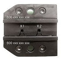
Crimpeinsatz
Art-Nr.
Crimp die
Order Code
600 618 326 200
600 618 326 200
600 618 326 200
600 618 326 200
600 619 228 180
600 619 228 180
600 619 228 180
600 619 228 180
600 649 326 160
600 649 326 160
600 649 326 160
600 649 326 160
600 649 326 160
600 649 326 160
600 662 324 200
600 662 324 200
600 662 324 200
600 662 324 200
Einstellung der Crimphöhe
Die Crimpkraft der Crimp-Systemzange ist vom
Werk eingestellt. Die Handkraft im Leerhub be-
trägt 130-180 N. Die Crimpmatrize und Hand-
zange sind so aufeinander abgestimmt, dass
bei dieser Handkraft ein optimaler Crimp er-
zeugt wird. Sollte das Crimpergebnis nicht der
geforderten Spezifikation des Verbinderherstel-
lers entsprechen (Crimphöhe, Auszugskraft), so
kann das folgende Ursachen haben:
a) Anwendungsbedingter Verschleiß der Zange
Nachjustierung der Crimpkraft möglich
b) Verschlissener Crimpeinsatz
ACHTUNG: Die Crimphöhe sollte regelmä-
ßig durch Fachpersonal der Qualitätskontrolle
überprüft und gegebenenfalls wie nachfolgend
beschrieben eingestellt werden:
um Schäden zu vermeiden, muss der
Crimpeinsatz ausgetauscht werden
A
B
1
2
3
4
Adjustment of the jaw spread
The crimp system tool’s crimping strength is
factory set. The hand force idle travel is 130-
180 N. The tool and die set are designed to
provide optimum crimping within this range.
However, if the setting is not ideal for the con-
nector manufacturer’s specifications (opening
and torque), one of the following problems could
be the reason:
a) Wear and tear due to excessive use of
Adjustment of the crimping strength
b) Worn dies
CAUTION: The crimping height (opening)
should be regularly checked by qualified tech-
nical personnel and set as described in the fol-
lowing:
Lösen Sie die Schaftschraube (A mit einem
Schraubendreher.
Loosen the headless screw (A) with a
screwdriver.
Wenn Sie die Stellscheibe (B) gegen den Uhr-
zeigersinn drehen (+), wird eine höhere Crimp-
kraft und eine kleinere Crimphöhe erreicht.
Turn the adjusting wheel (B) clockwise (+)
to increase the crimping force. This also
reduces the jaw spread.
Drehen Sie die Stellscheibe im Uhrzeigersinn
(-), so erhalten Sie eine geringere Crimpkraft
und somit eine größere Crimphöhe. Die Nach-
justierung der Handkraft sollte 180 N nicht
überschreiten.
Turn the dial clockwise (-) to reduce the
strength of the crimping force. This also
increases the jaw spread. Do exceed 180 N.
Vor Benutzung der Zange ist darauf zu achten,
dass die Stellscheibe ordnungsgemäß durch
die Schaftschraube gesichert ist.
After changing the setting, make sure the
headless screw is adequately tightened.
the tool
To avoid damage, the die set must
possible
be replaced
www.we-online.com
05