093.20 FINDER, 093.20 Datasheet - Page 2
093.20
Manufacturer Part Number
093.20
Description
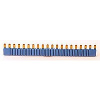
JUMPER LINK, 20WAY
Manufacturer
FINDER
Series
93r
Specifications of 093.20
Accessory Type
Jumper
No. Of Positions
20
Pitch Spacing
6.2mm
Svhc
No SVHC (15-Dec-2010)
Colour
Blue
Connector Type
Jumper (Busbar)
Current Rating
36A
Rohs Compliant
YES
For Use With
38 Series Relay Interface Modules
Lead Free Status / RoHS Status
Lead free / RoHS Compliant


38
2 Pole - 8 A electromechanical relay
interface modules, 14 mm wide.
Ideal interface for PLC and electronic systems
•
•
•
•
Features
116
38.52
38.62
Contact specification
Contact configuration
Rated current/Maximum peak current
Rated voltage/Maximum switching voltage V AC
Rated load AC1
Rated load AC15 (230 V AC)
Single phase motor rating (230 V AC)
Breaking capacity DC1: 30/110/220 V
Minimum switching load
Standard contact material
Coil specification
Nominal voltage (U
Rated power AC/DC
Operating range
Holding voltage
Must drop-out voltage
Technical data
Mechanical life
Electrical life at rated load AC1
Operate/release time
Insulation between coil and contacts (1.2/50 µs)
Dielectric strength between open contacts
Ambient temperature range
Protection category
Approvals relay (according to type)
Sensitive DC coil versions
Integral coil indication and protection circuit
Instant ejection of relay using plastic retaining clip
35 mm rail (EN 50022) mounting
14.3
14.3
5.6
5.6
N
)
16.7
17.3
18.8
36.7
38.1
19.4
56.1
19.3
57.6
71.6
71.6
19.4
19.4
VA (50 Hz)/W
19.5
mW (V/mA)
18.8
V AC/DC
17.3
AC/DC
AC/DC
AC/DC
cycles
cycles
V DC
V AC
kW
DC
VA
VA
ms
°C
kV
A
A
A1
•
•
•
A2
Screw terminal
2 pole electromechanical relay
35 mm rail mounting
38 Series - Relay interface modules 0.1 - 2 - 6 - 8 A
PROTECTION
INDICATION
CIRCUIT
(0.8...1.2)U
— / 0.05 U
2 CO (DPDT)
AND
8/0.3/0.12
12 - 24 - 60
— / 0.6 U
–40…+70
300 (5/5)
250/400
6 (8 mm)
30 · 10
80 · 10
38.52
—/0.5
2,000
1,000
8/15
AgNi
IP 20
400
0.3
—
—
—
6
3
N
N
N
A1
•
•
•
A2
Screwless terminal
2 pole electromechanical relay
35 mm rail mounting
PROTECTION
INDICATION
CIRCUIT
(0.8...1.2)U
— / 0.05 U
2 CO (DPDT)
AND
8/0.3/0.12
12 - 24 - 60
— / 0.6 U
–40…+70
300 (5/5)
250/400
6 (8 mm)
30 · 10
80 · 10
38.62
—/0.5
2,000
1,000
8/15
AgNi
IP 20
400
0.3
—
—
—
6
3
N
N
N
Related parts for 093.20
Image
Part Number
Description
Manufacturer
Datasheet
Request
R

Part Number:
Description:
CONNECTOR, RJI, IP20, CAT 6, WHITE
Manufacturer:
HARTING
Datasheet:


Part Number:
Description:
INTERFACE RELAY, SPDT-CO, 24VAC/DC
Manufacturer:
FINDER
Datasheet:
Part Number:
Description:
INTERFACE RELAY, SPDT-CO, 24VDC
Manufacturer:
FINDER
Datasheet: