Z7.282.0027.0 WIELAND ELECTRIC, Z7.282.0027.0 Datasheet - Page 127
Z7.282.0027.0
Manufacturer Part Number
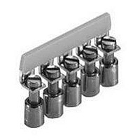
Z7.282.0027.0
Description
TERMINAL BLOCK JUMPER BAR, 40WAY, 8MM
Manufacturer
WIELAND ELECTRIC
Series
WK6r
Datasheet
1.07.311.0155.0.pdf
(900 pages)
Specifications of Z7.282.0027.0
Accessory Type
Jumper
No. Of Positions
40
Pitch Spacing
8mm
Row Pitch
8mm
For Use With
Wieland WK6/U Series DIN Rail Mount Terminal Blocks
Lead Free Status / RoHS Status
Lead free / RoHS Compliant


selos
*
)
WK 10/SI ... /U
fine stranded solid/stranded
1 – 10 mm
No. 22-6 AWG
No. 16-6 AWG
12 mm
i z r o + w d W
WK 10/Si U 5 x 20
WK 10/Si U 5 x 25
WK 10/Si U 5 x 30
WK 10/Si U 6,3 x 32
35 x 27 x 7,5 EN 60715
35 x 24 x 15 EN 60715
9006 EN 60715 G-32
WE 1/U
9708/2 S 35
9708
AP 10/Si
VB WK 10/Si-2
VB WK 10/Si-3
VB WK 10/Si-6
Screw cap made from thermoset type 131 and silver-
plated brass
Type
Voltage and current are determined by the
built-in LED and the inserted G-fuse.
9)
10)
1)
1)
6.3 A up to a power loss of 1.6 W
10 A up to a power loss of 2.5 W
2)
2)
2
3)
3)
2) - 8) 9) 10)
2) - 8) 9) 10)
2) - 8) 10)
1 – 16 mm
1) - 8) 10)
4)
4)
5)
5)
Part no.
57.910.5055.0
57.910.5155.0
57.910.5255.0
57.910.5355.0
98.300.0000.0
98.360.0000.0
98.190.0000.0
Z5.523.5753.0 100
Z5.522.8553.0 100
Z5.522.7053.0 100
07.311.4155.0
Z7.287.0227.0
Z7.287.0327.0
Z7.287.0627.0
04.312.2056.0 100
6)
6)
2
7)
7)
500 V/6 kV/3*
Std. pack
600 V*
600 V*
8)
8)
V
50
50
50
50
10
10
10
10
1
1
1
)
)
max. 15
13 mm
)
10*
15
A
)
*
WK 10/SI ... /U
fine stranded solid/stranded
1 – 10 mm
No. 22-6 AWG
No. 16-6 AWG
12 mm
i z r w d W
WK10/Si U 5 x 20M, NGL
WK10/Si U 5 x 20M, GLB
WK10/Si U 6,3 x 32M, NGL
WK10/Si U 6,3 x 32M, GLB
35 x 27 x 7,5 EN 60715
35 x 24 x 15 EN 60715
9006 EN 60715 G-32
WE 1/U
9708/2 S 35
9708
AP 10/Si
VB WK 10/Si-2
VB WK 10/Si-3
VB WK 10/Si-6
57.910.5453.0
Indicator
Current consumed: 0.16 – 0.8 mA
57.910.5853.0
Indicator
Current consumed: 24 mA
57.910.5753.0
Indicator
Current consumed: 0.16 – 0.8 mA
57.910.6153.0
Indicator
Current consumed: 24 mA
Lamp color of the indicator:
Type
)
Voltage and current are determined by the built-in indicator
and the inserted G-fuse.
7)
8)
1)
1)
6.3 A up to a power loss of 1.6 W
10 A up to a power loss of 2.5 W
2)
2)
2
3)
3)
1 – 16 mm
4)
4)
2)-6)7)8)
2)-6)7)8)
1) -6)8)
1)-6)8)
110 - 250 V
110 - 500 V
28 V
28 V
VDE
5)
5)
57.910.5455.0
57.910.5855.0
57.910.5755.0
57.910.6155.0
98.300.0000.0
98.360.0000.0
98.190.0000.0
Z5.523.5753.0 100
Z5.522.8553.0 100
Z5.522.7053.0 100
07.311.4155.0
Z7.287.0227.0
Z7.287.0327.0
Z7.287.0627.0
04.312.2056.0 100
10)
10)
Part no.
9)
with indicator
red,
6)
6)
2
9)
9)
10)
yellow
500 V/6 kV/3*
500 V
500 V
CSA
28 V
28 V
Std. pack
600 V*
600 V*
V
50
50
50
50
10
10
10
10
1
1
1
)
)
max. 15
13 mm
)
150 V
150 V
28 V
28 V
UL
max.
15
10*
A
)
Type
WK 10/SI U D
fine stranded solid/stranded
1 – 10 mm
No. 22-6 AWG
No. 16-6 AWG
12 mm
WK10/Si U D
35 x 27 x 7,5 EN 60715
35 x 24 x 15 EN 60715
9006 EN 60715 G-32
WE 1/U
9708/2 S 35
9708
AP 10/Si
VB WK 10/Si-2
VB WK 10/Si-3
VB WK 10/Si-6
2
1 – 16 mm
Part no.
57.910.4955.0
98.300.0000.0
98.360.0000.0
98.190.0000.0
Z5.523.5753.0 100
Z5.522.8553.0 100
Z5.522.7053.0 100
07.311.4155.0
Z7.287.0227.0
Z7.287.0327.0
Z7.287.0627.0
04.312.2056.0 100
2
500 V/6 kV/3
Std. pack
600 V
600 V
V
50
10
10
10
10
1
1
1
13 mm
57
50
65
125
A
Related parts for Z7.282.0027.0
Image
Part Number
Description
Manufacturer
Datasheet
Request
R


Part Number:
Description:
End Plate
Manufacturer:
WIELAND ELECTRIC
Datasheet:

Part Number:
Description:
END PLATE, WK SERIES TERMINAL BLOCK
Manufacturer:
WIELAND ELECTRIC
Datasheet:
Part Number:
Description:
END PLATE, WK/WKN SERIES TERMINAL BLOCK
Manufacturer:
WIELAND ELECTRIC
Datasheet:

Part Number:
Description:
PARTITION PLATE WK SERIES TERMINAL BLOCK
Manufacturer:
WIELAND ELECTRIC
Datasheet: