Z7.281.2227.0 WIELAND ELECTRIC, Z7.281.2227.0 Datasheet - Page 809
Z7.281.2227.0
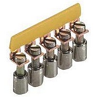
Manufacturer Part Number
Z7.281.2227.0
Description
TERMINAL BLOCK JUMPER BAR, 12WAY, 6MM
Manufacturer
WIELAND ELECTRIC
Series
WKr
Datasheet
1.Z7.281.7227.0.pdf
(900 pages)
Specifications of Z7.281.2227.0
Accessory Type
Jumper
No. Of Positions
12
Pitch Spacing
6mm
For Use With
12 Pole IVB WK 4-12 Terminal Blocks
Lead Free Status / RoHS Status
Lead free / RoHS Compliant


facts
Rated connecting capacity and connectable conductor
Table 1 (IEC 60 999-1: 2000)
Theoretical diameters of the largest conductor and ratio between the rated cross section and
connectable conductors
Table 1 (IEC 60 999-2: 1995)
* see IEC 60 999-1, table 1
The diameter of the largest rigid and flexible conductors are based on Table 1 of HD 383 (IEC 228A) and for AWG conductors are based on ASTM B172-71,
ICEA Publ. S-19-81 and ICEA Publ. S-66-516.
* Measurement only for flexible conductors of Class 5 according to HD 383 ( = IEC 228A, mod.), DIN VDE 0295
1)
2)
connecting
Nominal diameter + 5%
Largest diameter for conductors of Class I, K, M, + 5%
cross section
capacity
Rated
Rated
mm
0.50
0.75
10.0
16.0
25.0
35.0
mm
mm
1.0
1.5
2.5
4.0
6.0
35*
120
150
185
240
300
50
70
95
–
–
–
2
2
2
mm
0.75
10.0
16.0
25.0
35.0
0.5
1.0
1.5
2.5
4.0
6.0
2
stranded
11.0
12.9
14.5
16.2
18.0
20.6
23.1
rigid
mm
mm
7.9
9.1
–
–
–
solid
rigid
Ø mm
0.9
1.0
1.2
1.5
1.9
2.4
2.9
3.7
4.6
–
–
Metric
Connectable conductors and their theoretical diameters
stranded
Ø mm
flexible
Class 5
7 .9
1.1
1.2
1.4
1.7
2.2
2.7
3.3
4.2
5.3
6.6
17 .0
27 .0
11.0
13.1
15.1
19.0
21.0
24.0
mm
mm
9.2
–
–
Theoretical diameter of the largest conductor
Metric
mm
0.75
10.0
16.0
25.0
0.5
1.0
1.5
2.5
4.0
4.0
6.0
2
flexible
Gauge
0000
000
250
300
350
400
500
600
00
2
1
0
Ø mm
2.3*
2.9*
2.9*
7 .8
1.1
1.3
1.5
1.8
3.9
5.1
6.3
Gauge
20
18
16
14
12
10
–
8
6
4
2
AWG/Kcmil
stranded
11.17
12.54
14.08
15.34
16.80
18.16
19.42
21.68
23.82
7 .78
rigid
8.85
9.64
mm
mm
Ø mm
solid
rigid
0.85
1.07
1.35
1.71
2.15
2.72
3.43
4.32
5.45
6.87
1)
1)
–
AWG/Kcmil
stranded
Class B
flexible
Ø mm
17 .22
AWG
10.61
12.08
13.54
15.33
19.01
20.48
22.05
24.05
26.57
30.03
7 .78
0.97
1.23
1.55
1.95
2.45
3.09
3.89
4.91
6.18
9.02
mm
mm
1)
1)
–
20
18
16
14
12
10
–
–
8
6
4
is to be indicated
in the appropriate
specifications
Connectable
flexible
equipment
conductor
Class I, K, M
stranded
Ø mm
7 .26
1.02
1.28
1.60
2.08
2.70
3.36
4.32
5.73
2)
–
–
807
Related parts for Z7.281.2227.0
Image
Part Number
Description
Manufacturer
Datasheet
Request
R


Part Number:
Description:
End Plate
Manufacturer:
WIELAND ELECTRIC
Datasheet:

Part Number:
Description:
END PLATE, WK SERIES TERMINAL BLOCK
Manufacturer:
WIELAND ELECTRIC
Datasheet:
Part Number:
Description:
END PLATE, WK/WKN SERIES TERMINAL BLOCK
Manufacturer:
WIELAND ELECTRIC
Datasheet:

Part Number:
Description:
PARTITION PLATE WK SERIES TERMINAL BLOCK
Manufacturer:
WIELAND ELECTRIC
Datasheet: