88-569766-32S Amphenol, 88-569766-32S Datasheet - Page 29
88-569766-32S
Manufacturer Part Number
88-569766-32S
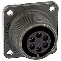
Description
CIRCULAR CONN RCPT SIZE 19, 32POS, PANEL
Manufacturer
Amphenol
Series
MIL-DTL-38999 Series IIIr
Datasheet
1.88-569761-35P.pdf
(53 pages)
Specifications of 88-569766-32S
Gender
Receptacle
Contact Gender
Socket
Connector Mounting
Panel
Connector Shell Size
19
Insert Arrangement
19-32
Connector Type
Circular Industrial


Cylindrical Connectors with PCB contacts
alternate positioning available
for MIL-DTL-38999 connectors
To avoid cross-plugging problems in applications requiring the use of more than one connector of the same series, size and arrange-
ment, alternate rotations are available as indicated in the accompanying charts.
In MIL-DTL-38999 Series I, II and III connectors the rotation is based on rotating the master key/keyway in the connector shell.
A plug with a given rotation letter will mate with a receptacle with the same rotation letter. Only the master key/keyway rotates in the
shell, and the insert always remains in the same position relative to the minor keys. Refer to diagrams below for each connector series.
LJT (MIL-DTL-38999 Series I) KEY/KEYWAY ROTATION
JT (MIL-DTL-38999 Series II) KEY/KEYWAY ROTATION
Tri-Start (MIL-DTL-38999 Series III) KEY/KEYWAY ROTATION
11, 13,
and 15
17 and
21, 23,
and 25
Shell
Size
19
Shell
Shell
9
Size
Size
11
13
15
17
19
21
23
25
10
12
14
16
18
20
22
24
9
8
Identification Letter
Key & Keyway
Arrangement
Normal°
Normal°
AB ANGLE OF ROTATION (Degrees)
AB ANGLE OF ROTATION (Degrees)
100
100
100
100
100
100
100
100
100
95
95
95
95
95
95
95
95
95
N
A
B
C
D
E
N
A
B
C
D
E
N
A
B
C
D
E
N
A
B
C
D
E
A°
77
81
75
74
77
77
77
80
80
A°
82
86
80
79
82
82
82
85
85
BSC
AR°
105
102
113
119
135
135
80
35
64
91
95
90
53
51
80
49
66
62
79
80
49
66
62
79
B°
67
63
61
65
65
65
69
69
B°
72
68
66
70
70
70
74
74
–
–
BSC
BR°
140
132
118
140
155
131
141
156
145
156
146
141
142
170
169
140
145
153
142
170
169
140
145
153
123
127
129
125
125
125
121
121
128
132
134
130
130
130
126
126
C°
C°
BSC
–
–
CR°
215
248
230
205
234
197
208
182
195
220
176
184
196
200
200
200
180
197
196
200
200
200
180
197
113
109
115
116
113
113
113
110
110
118
114
120
121
118
118
118
115
115
BSC
DR°
265
320
312
275
304
240
236
292
252
255
298
242
293
310
244
257
280
272
293
310
244
257
280
272
D°
D°
(front face of Tri-Start connector receptacle shown)
(front face of LJT connector receptacle shown)
(front face of JT connector receptacle shown)
10 JT REF
5 LJT REF
AB
AB
25
˚
˚
OF ROTATED MASTER KEYWAY
OF ROTATED MASTER KEYWAY
OF ROTATED MASTER KEYWAY
RELATIVE POSSIBLE POSITION
RELATIVE POSSIBLE POSITION
RELATIVE POSSIBLE POSITION
BR
BSC
DR
BSC
˚
˚
AR
BSC
B
B
˚
A
A
NORMAL
NORMAL
CR
BSC
˚
MAIN
KEYWAY
D
D
C
C
ROTATION
LETTERS
ROTATION
LETTERS
Explanation:
Use P at end of part number for pin
contacts in Normal position.
Use S at end of part number for
socket contacts in Normal position.
Use cross reference letters given in
chart above for alternate rotations.
ALTERNATE ROTATION CROSS
Explanation:
Use P at end of part number for pin
contacts in Normal position.
Use S at end of part number for
socket contacts in Normal position.
Use cross reference letters given in
chart above for alternate rotations.
ALTERNATE ROTATION CROSS
Rotations
Alternate
TRI-START CONNECTORS
LJT & JT CONNECTORS
Rotations
PC = W
Alternate
REFERENCE LETTERS
Pins in
PA = E
PB = R
PD = Y
PD = M
REFERENCE LETTERS
Pins in
PA = G
PC = K
PE = R
PB = I
Sockets in
Rotations
Alternate
Sockets in
Rotations
Alternate
SC = X
SD = Z
SA = F
SB = T
SA = H
SD = N
SB = J
SC = L
SE = T
Related parts for 88-569766-32S
Image
Part Number
Description
Manufacturer
Datasheet
Request
R

Part Number:
Description:
Cable Specification: PU CABLE, UL20549 24AWG*8C+AD,OD= 6.0mm
Manufacturer:
Amphenol
Part Number:
Description:
BEN44-104-10005-2 5 WAY 44 RECEPTACLE INSULATOR
Manufacturer:
Amphenol