0932-0-15-20-77-14-11-0 Mill-Max Manufacturing Corp., 0932-0-15-20-77-14-11-0 Datasheet
0932-0-15-20-77-14-11-0
Manufacturer Part Number
0932-0-15-20-77-14-11-0
Description
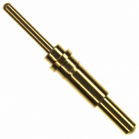
CONN PIN SPRING-LOAD .472 20GOLD
Manufacturer
Mill-Max Manufacturing Corp.
Series
0932r
Datasheets
1.0906-1-15-20-75-14-11-0.pdf
(1 pages)
2.0906-1-15-20-75-14-11-0.pdf
(1 pages)
3.0932-0-15-20-77-14-11-0.pdf
(2 pages)
Specifications of 0932-0-15-20-77-14-11-0
Plating
Gold
Plating - Thickness
20µin (0.51µm)
Mounting Type
Through Hole
Product Type
Contacts
Contact Gender
Pin (Male)
Mounting Style
Through Hole
Mounting Angle
Vertical
Latching Type
Unlatched
Termination Style
Solder Pin
Housing Material
Copper Alloy
Contact Material
Copper Alloy
Contact Plating
Gold over Nickel
Current Rating
3 A
Connector Tip Style
Point
Overall Length
0.472"
Spring Force Initial
25g
Lead Free Status / RoHS Status
Lead free / RoHS Compliant
Other names
0932015207714110
ED90345
ED90345
w w w. m i l l - m a x . c o m
Solder mount in 0,46 min. mounting hole
Solder mount in 0,69 min. mounting hole
Solder mount in 0,69 min. mounting hole
1,07 DIA.
1,07 DIA.
1,5 DIA.
1,5 DIA.
1,63 DIA.
1,63 DIA.
1,78 DIA.
1,78 DIA.
1,4 DIA.
1,4 DIA.
0,64 DIA.
0,64 DIA.
1,07 DIA.
1,07 DIA.
1,5 DIA.
1,5 DIA.
1,63 DIA.
1,63 DIA.
1,83 DIA.
1,83 DIA.
0,43 DIA.
0,43 DIA.
1,07 DIA.
1,07 DIA.
1,5 DIA.
1,5 DIA.
1,63 DIA.
1,63 DIA.
1,83 DIA.
1,83 DIA.
1,4 DIA.
1,4 DIA.
0,64 DIA.
0,64 DIA.
0906-0
0914
0901
0906-0-15-20-76-14-11-0
0914-0-15-20-77-14-11-0
0901-0-00-00-00-00-11-0
ORDER CODE: 09XX - X - 15 - 20 - 7X - 14 - 11 - 0
TOLERANCES ON: LENGTHS:
SLEEVE & PLUNGER MATERIAL: Copper Alloy
SPRING MATERIAL: Beryllium Copper
SLEEVE & PLUNGER FINISH: 0,51 μm Gold over Nickel
SPRING FINISH: 0,25 μm Gold over Nickel
DIMENSION IN INCHES:
Standard Stroke
Short Stroke
Long Stroke
0,41
0,41
0,71
0,71
0,71
0,71
MATERIAL SPECIFICATIONS:
0,41
0,41
0,41
0,41
1,14
1,14
Spring Number
DIAMETERS: ±0,05
ANGLES:
0,5
0,5
0,71
0,71
0,7
0,7
0,71
0,71
0,71
0,71
5,74
5,74
4,7
4,7
2,29
2,29
5,38
5,38
2,92
2,92
0,99
0,99
2,49
2,49
1,75
1,75
6,12
6,12
1,32
1,32
1,4
1,4
±0,15
± 2°
Solder Mount in 0,69 min. mounting hole
Solder Mount in 0,69 min. mounti
0932
0929
0906-1⇒ ⇒ 4
1,07 DIA.
1,07 DIA.
1,5 DIA.
1,5 DIA.
1,63 DIA.
1,63 DIA.
1,83 DIA.
1,83 DIA.
1,4 DIA.
1,4 DIA.
0,64 DIA.
0,64 DIA.
0932-0-15-20-77-14-11-0
0929-0-15-20-75-14-11-0
1,07 DIA.
1,07 DIA.
1,5 DIA.
1,5 DIA.
1,63 DIA.
1,63 DIA.
1,83 DIA.
1,83 DIA.
0,43 DIA.
0,43 DIA.
1,07 DIA.
1,07 DIA.
1,5 DIA.
1,5 DIA.
1,63 DIA.
1,63 DIA.
1,83 DIA.
1,83 DIA.
1,5 DIA.
1,5 DIA.
0,64 DIA.
0,64 DIA.
Discrete Spring-Loaded Contacts
SPRING-LOADED CONNECTORS
Standard Stroke
Long Stroke
0,7
0,7
1,1
1,1
0,71
0,71
1,1
1,1
Solder mount in 0,46 min. mounting hole
0906-X-15-20-75-14-11-0
1,2
1,2
0,41
0,41
2002/95/EC
RoHS
0,41
0,41
0,71
0,71
1,4
1,4
0,71
0,71
2,3
2,3
0,7
0,7
5,8
5,8
6,0
6,0
ng Hole
Standard Stroke
4,7
4,7
4,3
4,3
0,71
0,71
14,6
14,6
12
12
16
2,69
2,69
1,4
1,4
Solder mount in 0,69 min. mounting hole
0922
0908-0⇒ ⇒ 9
1,07 DIA.
1,07 DIA.
1,5 DIA.
1,5 DIA.
1,63 DIA.
1,63 DIA.
1,83 DIA.
1,83 DIA.
1,52 DIA.
1,52 DIA.
0,64 DIA.
0,64 DIA.
NUMBER
0922-0-15-20-75-14-11-0
SPRING
1,75
1,75
1,07 DIA.
1,07 DIA.
1,5 DIA.
1,5 DIA.
1,63 DIA.
1,63 DIA.
1,83 DIA.
1,83 DIA.
0,43 DIA.
0,43 DIA.
75
76
77
A
Basic Part
MECHANICAL & ELECTRICAL SPECIFICATIONS:
0906-1
0906-2
0906-3
0906-4
Standard Stroke
Number
75, 76, 77 Springs are not Interchangeable
CURRENT RATING: 2A continuous, 3A peak
0,71
0,71
STROKE
CONTACT RESISTANCE: 20 mΩ max.
Solder mount in 0,46 min. mounting hole
0,7
0,7
Mid.
1,14
0,7
0,5
0908-X-15-20-75-14-11-0
1,17
1,17
DURABILITY: 1,000,000 cycles
0,41
0,41
0,7
0,7
Length
1,96
1,96
5,51
5,99
4,5
5,0
STROKE
STROKE
A
0,71
0,71
MID
MID
7,75
7,75
Standard Stroke
1,4
1,4
1,4
1,4
5,08
5,08
8,13
8,13
STROKE
Max.
0,99
2,29
STROKE
STROKE
1,4
5,03
5,03
MAX
MAX
Solder Mount in 0,46 min. mounting hole
1,07 DIA.
1,07 DIA.
1,5 DIA.
1,5 DIA.
1,63 DIA.
1,63 DIA.
1,83 DIA.
1,83 DIA.
0,7 DIA.
0,7 DIA.
0930
Double action, *1,4 Combined Stroke
Mount between parallel circuit boards
1,07 DIA.
1,07 DIA.
1,5 DIA.
1,5 DIA.
1,63 DIA.
1,63 DIA.
1,83 DIA.
1,83 DIA.
0,43 DIA.
0,43 DIA.
0980
0930-0-15-20-75-14-11-0
0980-0-15-20-75-14-11-0
1,75
1,75
A
5 1 6 - 9 2 2 - 6 0 0 0
Mid. Stroke
FORCE @
Basic Part
Standard Stroke
0908-0
0908-1
0908-2
0908-3
0908-4
0908-5
0908-6
0908-7
0908-8
0908-9
Number
60 g
60 g
60 g
0,41
0,41
0,7
0,7
0,7
0,7
0,41
0,41
0,71
0,71
Length
10,41
10,92
Initial Force
6,48
6,99
7,49
8,51
8,89
9,91
0,38
0,38
(Pre-load)
1,4
1,4
8,0
9,4
A
0,7
0,7
25 g
25 g
25 g
0,64
0,64
PINS
2,7
2,7
1,3
1,3
5,0
5,0
1,3
1,3
5,1
5,1
7,6
7,6
Related parts for 0932-0-15-20-77-14-11-0
Image
Part Number
Description
Manufacturer
Datasheet
Request
R

Part Number:
Description:
CONN SPRING LOADED PIN .177 GOLD
Manufacturer:
Mill-Max Manufacturing Corp.
Datasheet:

Part Number:
Description:
CONN SPRING LOADED PIN .197 GOLD
Manufacturer:
Mill-Max Manufacturing Corp.
Datasheet:

Part Number:
Description:
CONN SPRING LOADED PIN .236 GOLD
Manufacturer:
Mill-Max Manufacturing Corp.
Datasheet:

Part Number:
Description:
CONN SPRING LOADED PIN .217 GOLD
Manufacturer:
Mill-Max Manufacturing Corp.
Datasheet:

Part Number:
Description:
CONN SPRING LOADED PIN .137 GOLD
Manufacturer:
Mill-Max Manufacturing Corp.
Datasheet:
