10250-1210PE 3M, 10250-1210PE Datasheet - Page 3
10250-1210PE
Manufacturer Part Number
10250-1210PE
Description
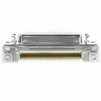
CONN MDR RECEPT 50POS R/A SMD
Manufacturer
3M
Series
102, Mini D Ribbon (MDR)r
Datasheet
1.10214-1210PE.pdf
(6 pages)
Specifications of 10250-1210PE
Connector Style
Outer Shroud Contacts
Connector Type
Receptacle
Number Of Positions
50
Number Of Rows
2
Mounting Type
Surface Mount, Right Angle
Termination
Solder
Flange Feature
Insert, Threaded (M2.5)
Features
Latch Lock, Shielded
Contact Finish
Gold
Contact Finish Thickness
20µin (0.51µm)
Product
Micro Hoods & Connectors
Number Of Positions / Contacts
50
Current Rating
1 A
Contact Plating
Tin Lead
Mounting Style
SMD/SMT
Mounting Angle
Right
Termination Style
Solder Pad
Contact Material
Copper Alloy
Housing Material
Glass Filled Polyester
Operating Temperature Range
- 55 C to + 105 C
Lead Free Status / RoHS Status
Lead free / RoHS Compliant
Other names
10250-1210PE
102501210PE
3M1826
4547452262014
54745226201
JE150317822
102501210PE
3M1826
4547452262014
54745226201
JE150317822


3M
.050″ Surfacemount Right Angle Receptacle - Shielded
3
Interconnect Solutions
http://www.3M.com/interconnects/
Quantity
Contact
Quantity
Contact
14
20
26
40
50
14
20
26
40
50
50 Pos.
Last
Pos.
Pos.
40 Pos.
Last
20 Pos.
26 Pos.
14 Pos.
Last
Pos.
Pos.
Last
Solder Pad and Contact Numbering Detail
(Pad numbers correspond to connector contact numbers shown on previous page)
™
1.081 [ 27.45 ]
1.230 [ 31.26 ]
1.581 [ 40.15 ] 1.150 [ 29.21 ]
1.831 [ 46.50 ] 1.400 [ 35.56 ]
.931 [ 23.64 ]
Pos.
Last
A ± .002
1.09 [ 27.6 ]
1.44 [ 36.5 ]
1.69 [ 42.8 ]
50
.78 [ 19.9 ]
.94 [ 23.8 ]
40 39 38 37 36 35 34 33 32 31
25
26
20
Mini D Ribbon (MDR) Connectors
14 13
49
20 19 18
D
13
24
10
7
25 24
19 18 17 16 15 14 13 12
48
12 11
23
6
PCB Ref. Edge
9
.500 [ 12.70 ]
.650 [ 16.51 ]
.800 [ 20.32 ]
47
Dimensions
12
B ± .002
22 21
1.081 [ 27.45 ]
1.231 [ 31.26 ]
1.581 [ 40.15 ]
1.830 [ 46.50 ]
.931 [ 23.64 ]
46
5
8
23
11
10
17 16 15
PCB Ref. Edge
45
22 21 20 19 18 17 16 15 14
E
4
7
20
9
10
44
PCB Ref. Edge
3
19 18 17 16 15 14 13
6
1.225 [ 31.12 ]
8
.475 [ 12.07 ]
.625 [ 15.88 ]
.975 [ 24.77 ]
43 42 41 40 39 38 37 36 35
.325 [ 8.26 ]
9
C ± .002
2x .122 [ 3.1 ]
2x .138 [ 3.5 ]
2x .256 [ 6.5 ]
2
5
7
14 13
PCB Ref. Edge
8
PCB Ref. Edge
1
4
6
11
5
3
30 29 28 27 26 25 24 23 22 21
12
PCB Ref. Edge
.0250 ± .0008 [ 0.64 ]
10 9
4
Position
(Bottom Row)
2
11
Connector Position
(Top Row)
center spacing
.118 [ 3.0 ]
3
1
8
[ 1.50 ]
R .060
2
12
7
1
11
Recommended Board Layout
6
Position
(Bottom Row)
10
Connector Position
(Top Row)
5
34
9
.088 [ 2.223 ]
Position
(Bottom Row)
4
33 32 31 30 29 28 27 26
Connector Position
(Top Row)
Notes:
8
Note: Panel thickness .079 [ 2.00 ] Max.
Recommended Panel Cut-out
(viewed from connector side)
3
means during the soldering process. To prevent soldering defects, the
screws (M2.5) should not be tightened excessively.
soldering. The connector should be fixed to the panel with panel mount
screws or jack sockets. See TS-0142 for mounting hardware.
1. Plated through mounting holes for .062
2. The connector should be fixed to the PCB by screws, tools or other
3. The connector must be fixed to the PCB by board lock screws after
7
center spacing
2
6
1
5
C
For technical, sales or ordering information call
A
B
.165 [ 4.2 ]
4
D ± .004
E ± .004
Connector
Position
(Bottom Row)
Position
3
[ 4.75 ]
.187 max.
2
3M is a trademark of 3M Company.
1
Position
(Bottom Row)
.0158 ± .0004 [ 0.40 ]
Connector
Position
.093 ± .004 [ 2.36 ]
″
Solder Pads for Solder
Tail (See below for
more detail)
[1.57] board thickness.
.319 ± .004
[ 8.1 ]
∅ .079 + .004 (2X)
Positioning Hole
102 Series
800-225-5373
∅ .110 ± .004 (2X)
Screw Lock
(see notes below)
Lockstand Solder
Pad Outline
- .000
TS-0755-C
Sheet 3 of 3
Related parts for 10250-1210PE
Image
Part Number
Description
Manufacturer
Datasheet
Request
R

Part Number:
Description:
CONN MDR RECPT 50POS VERT T/H
Manufacturer:
3M
Datasheet:
Part Number:
Description:
CONN MDR RCPT 50POS R/A 4-40
Manufacturer:
3M
Datasheet:

Part Number:
Description:
CONN MDR RCPT 50POS R/A SMD 20AU
Manufacturer:
3M
Datasheet:

Part Number:
Description:
CONN MDR RECPT 50POS IDC GOLD
Manufacturer:
3M
Datasheet:

Part Number:
Description:
CONN MINI-D 50POS R/A RECPT
Manufacturer:
3M
Datasheet:

Part Number:
Description:
3M-MINI-CLAMP/PLUG/WMIC/2MM/3POS/TYPE A/ORANGE/3M LOGO
Manufacturer:
3M
Datasheet:
Part Number:
Description:
3M-MINI-CLAMP/PLUG/WMIC/2MM/4POS/TYPE A/YELLOW/3M LOGO
Manufacturer:
3M
Datasheet:
Part Number:
Description:
3M-MINI-CLAMP/PLUG/WMIC/2MM/4POS/TYPE A/ORANGE/3M LOGO
Manufacturer:
3M
Datasheet:
Part Number:
Description:
3M-MINI-CLAMP/SKT PANELMOUNT/WMIC/2MM/3POS/TYPE A/RED/3M LOGO
Manufacturer:
3M
Datasheet:
Part Number:
Description:
3M-MINI-CLAMP/SKT PANELMOUNT/WMIC/2MM/3POS/TYPE A/YELLOW/3M LO
Manufacturer:
3M
Datasheet:
Part Number:
Description:
3M-MINI-CLAMP/SKT/WMIC/2MM/3POS/TYPE A/ORANGE/3M LOGO
Manufacturer:
3M
Datasheet:
Part Number:
Description:
3M-MINI-CLAMP/SKT PANELMOUNT/WMIC/2MM/3POS/TYPE A/ORANGE/3M LO
Manufacturer:
3M
Datasheet:
Part Number:
Description:
3M-MINI-CLAMP/SKT PANELMOUNT/WMIC/2MM/4POS/TYPE A/RED/3M LOGO
Manufacturer:
3M
Datasheet:
Part Number:
Description:
3M-MINI-CLAMP/SKT/WMIC/2MM/4POS/TYPE A/YELLOW/3M LOGO
Manufacturer:
3M
Datasheet: