LF13WBP-20S HRS (HIROSE), LF13WBP-20S Datasheet
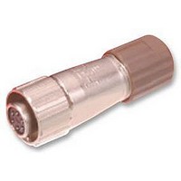
LF13WBP-20S
Specifications of LF13WBP-20S


Related parts for LF13WBP-20S


LF13WBP-20S Summary of contents
Page 1
The product information in this catalog is for reference only. Please request the Engineering Drawing for the most current and accurate design information. All non-RoHS products have been discontinued, or will be discontinued soon. Please check the products status on ...
Page 2
The product information in this catalog is for reference only. Please request the Engineering Drawing for the most current and accurate design information. All non-RoHS products have been discontinued, or will be discontinued soon. Please check the products status on ...
Page 3
... Part number CL No. LF07WBP-3S 136-0003-7 LF07WBP-3P 136-0004-0 LF07WBP-6S 136-0001-1 LF07WBP-6P 136-0002-4 LF10WBP-4S 136-0005-2 LF10WBP-4P 136-0006-5 LF10WBP-12S 136-0007-8 LF10WBP-12P 136-0008-0 LF13WBP-20S 136-0009-3 LF13WBP-20P 136-0010-2 LF13WBP-11S 136-0011-5 LF13WBP-11P 136-0012-8 ■Receptacles Part number CL No. LF07WBR-3P 136-1003-2 LF07WBR-3S 136-1004-5 LF07WBR-6P 136-1001-7 LF07WBR-6S 136-1002-0 LF10WBR-4P ...
Page 4
The product information in this catalog is for reference only. Please request the Engineering Drawing for the most current and accurate design information. All non-RoHS products have been discontinued, or will be discontinued soon. Please check the products status on ...
Page 5
... Note 2: The ▼ symbol indicates polarizing key position. Note 3: Withstanding voltages are test voltage values. Description Manual cable clamp crimp Note: Applicable cable dia. is only 5mm for LF series. Applicable connectors LF07WBP-6S,6P,3S,3P LF07WBJ-6S,6P,3S,3P LF10WBP-4S,4P,12S,12P LF10WBJ-4S,4P,12S,12P LF13WBP-20S,20P,11S,11P LF13WBJ-20S,20P,11S,11P Shell size LF07 LF10 LF13 +0. LF07 ...
Page 6
... Insert the plug into securely held solder termination fixture as shown. Fixture Part No. Applicable connector LF07BP-T01 LF07WBP-6S,6P,3S,3P LF10BP-T01 LF10WBP-4S,4P,12S,12P LF13BP-T01 LF13WBP-20S,20P,11S,11P 2 Loosen the backshell turning it counter clockwise and remove it from the body/ insulator assembly. Jack Disassembly 1 Insert the jack into the securely held solder termination fixture as shown ...
Page 7
The product information in this catalog is for reference only. Please request the Engineering Drawing for the most current and accurate design information. All non-RoHS products have been discontinued, or will be discontinued soon. Please check the products status on ...
Page 8
The product information in this catalog is for reference only. Please request the Engineering Drawing for the most current and accurate design information. All non-RoHS products have been discontinued, or will be discontinued soon. Please check the products status on ...
Page 9
The product information in this catalog is for reference only. Please request the Engineering Drawing for the most current and accurate design information. All non-RoHS products have been discontinued, or will be discontinued soon. Please check the products status on ...
Page 10
... Place the body/insulator assembly in the applicable solder termination fixture. For plug assembly Fixture Part No. Applicable connector LF07BP-T01 LF07WBP-6S,6P,3S,3P LF10BP-T01 LF10WBP-4S,4P,12S,12P LF13BP-T01 LF13WBP-20S,20P,11S,11P For jack assembly Applicable connector Fixture Part No. LF07BJ-T01 LF07WBJ-6S,6P,3S,3P LF10BJ-T01 LF10WBJ-4S,4P,12S,12P LF13BJ-T01 LF13WBJ-20S,20P,11S,11P 2 Coat the thread section of the body/insulator assembly with Loctite 271 compound (manufactured by Henckel Japan, Ltd ...
Page 11
The product information in this catalog is for reference only. Please request the Engineering Drawing for the most current and accurate design information. All non-RoHS products have been discontinued, or will be discontinued soon. Please check the products status on ...