97-3107A-20(0850) Amphenol Industrial Operations, 97-3107A-20(0850) Datasheet - Page 62
97-3107A-20(0850)
Manufacturer Part Number
97-3107A-20(0850)
Description
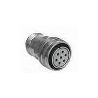
CIRCULAR SHELL, PLUG, SIZE 20, AL ALLOY
Manufacturer
Amphenol Industrial Operations
Type
Plug Shell Onlyr
Specifications of 97-3107A-20(0850)
Connector Shell Size
20
Connector Body Material
Aluminum Alloy
Circular Shell Style
Quick Disconnect Plug
Connector Type
Circular Industrial
Agency Approvals
UL/CSA
Angle
Straight
Application
Commercial
Brand/series
97 Series
Class
A
Finish, Housing
Olive Drab Cadmium
Housing Type
Metal
Material, Housing
Aluminum Alloy
Mating Type
Quick Disconnect
Mounting Type
Free Hanging
Primary Type
5015 Commercial
Shell Size
20
Strain Relief
Solid
Shell Type
Solid Shell Quick Disconnect Plug
Body Material
Aluminum Alloy
For Use With
97 Series Circular Connectors


Assembly Instructions
for 10-305200 & 10-74900 cable clamps
The 10-305200 cable clamp and MS3420A sleeve illustrated are used only on
the rear of MS-A or C type connectors. The 10-74900 clamp and grommet
assembly can only be used on special feed-thru applications involving dummy
shells, part numbers 10-37090 and 10-113276.
10-305200 Cable Clamp & MS3420A Sleeve
10-74900 Clamp and Grommet Assembly
4
3
3
2
1. Clamping Nut
2. Tapered Sleeve
3. Grommet
1. Clamping Nut
2. Tapered Sleeve
3. Gland
4. Reducing or
2
Telescoping Sleeve
1
1
61
ASSEMBLY
Both clamps are shipped from the factory with lubricant
conforming to MIL-G-3278. Remove any dirt or foreign
material from components with ethyl alcohol and relubri-
cate as outlined under “lubrication.” Place the clamping
nut (1) on the wire bundle or cable with the threads facing
toward the connector or dummy shell. Position the
tapered sleeve (2) on the bundle or cable with the narrow
portion toward the clamping nut (1). Next install either the
gland (3) used with the 10-305200 clamp or thread each
wire through the grommet (3) used with the 10-74900
clamp. Dependent on the application, the wire bundle or
cable is fed through the dummy shell, or the wire ends
are soldered to the connector contacts. Move the compo-
nents forward in the reverse order of preliminary assem-
bly. (In applications where grommets (3) are used, seat
the grommet against the undercut in the back shell
before bringing the tapered sleeve (2) up against it).
Insure proper positioning of glands (3) or grommets (3),
tapered sleeves (2) and clamping nuts (1). Tighten the
clamp using a strap wrench until a metal to metal seat is
obtained.
Related parts for 97-3107A-20(0850)
Image
Part Number
Description
Manufacturer
Datasheet
Request
R

Part Number:
Description:
connector, metal circ, str plug, qd, size 12s, 2 #16 solder socket cont, olive drab
Manufacturer:
Amphenol Industrial Operations
Datasheet:
Part Number:
Description:
connector, metal circ, str plug, QD, size 24, 2 #4 solder socket contact, olive drab
Manufacturer:
Amphenol Industrial Operations
Datasheet:
Part Number:
Description:
connector, metal circ, str plug, QD, size 16, 2#12, 2#16 solder socket cont, olive drab
Manufacturer:
Amphenol Industrial Operations
Datasheet:
Part Number:
Description:
connector, metal circ, str plug, QD, size 18, 2 #12 solder socket contact, olive drab
Manufacturer:
Amphenol Industrial Operations
Datasheet:
Part Number:
Description:
connector, metal circ, str plug, QD, size 22, 2 #16 solder pin contact, olive drab
Manufacturer:
Amphenol Industrial Operations
Datasheet:

Part Number:
Description:
JAM NUT CONN, RCPT, SIZE 9, 6POS, PANEL
Manufacturer:
Amphenol Industrial Operations
Datasheet:
Part Number:
Description:
PT 41C 41#20 PIN RECP
Manufacturer:
Amphenol Industrial Operations
Part Number:
Description:
PT 41C 41#20 SKT RECP
Manufacturer:
Amphenol Industrial Operations