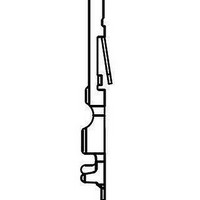
02 05 000 2512 HARTING, 02 05 000 2512 Datasheet

02 05 000 2512
Specifications of 02 05 000 2512
Related parts for 02 05 000 2512
02 05 000 2512 Summary of contents
Page 1
Directory chapter 02 VMEbus systems . . . . . . . . . . . . . . . . . . . . . . . . . . . . . . . . . . . ...
Page 2
... Mbyte/s (VME 64x), HARTING introduced is 100 % backwards compatible to existing 3 row connectors with 96 contacts, therefore old can plug into new. To offer the best design possible from the start, HARTING developed spice models that were later certified via signal integrity measurements of the connector. High precision slot structure with VME 02 ...
Page 3
System description Backward compatibility The design of female connectors allows mating of any combinations of the row versions without mechanical interference, thus making it possible for users to upgrade and maintain existing systems at lower costs. It ...
Page 4
System description The advantages of User-defined pins in the outer rows can be used for application specific functions such as additional I/O. Configured as a shield to provide larger ground return paths, they assure for data transfer rates up to ...
Page 5
The insulator, made of LCP, has an inherent flammability rating of UL 94-V0 and therefore provides an environment friendly connector. In addition, the heat deformation stability of LCP makes the connector surface-mount compatible (see chapter 00). Partially gold plated terminations ...
Page 6
System description Bridging variants: 1. The empty card slots may be assembled with dummy cards, that bridge the daisy-chain lines. 2. Bridging can be 5 jumpers on the back plane manually. 3. Bridging by using IC's with internal integration OR ...
Page 7
Integrated switching element Status: daughter card unmated Advantages: Passive backplane; no active components ● assembled No additional space required, due to ● integrated switching function inside the connector No jumpers on the backplane ● User friendly regarding maintenance and ● ...
Page 8
Technical characteristics Number of contacts Contact spacing (mm) Working current see current carrying capacity chart Clearance and creepage distances minimal clearance and creepage distance clearance between two rows creepage clearance between two contacts (in a row) creepage Working voltage The ...
Page 9
IEC 61 076 - 4 - 113 Number of contacts 160 Male connectors, angled, SMC compatible Number Identification of contacts Male connector* 160 without retention clip with retention clip 160 Dimensions Board drillings Mounting side row Cross section of ...
Page 10
IEC 61 076 - 4 - 113 Number of contacts 160 Female connectors Identification Female connectors, straight 2) with press-in terminations with 3.7 mm* * fixing flange 4 mm mm* without 5 mm* * fixing ...
Page 11
IEC 61 076 - 4 - 113 Number of contacts 160 Female connectors Number Identification of contacts Female connectors, straight with switches 2) with press-in terminations with flange 4 160 Dimensions Board drillings Mounting ...
Page 12
IEC 61 076 - 4 - 113 Number of contacts 160 Female connectors Identification Female connectors, angled with solder pins for rear access for har-bus ® 64 male connector Dimensions 02 04 160 1101 Dimensions 02 07 ...
Page 13
... Suitable for har-bus Male connector type R with 5 rows Male connector type C with 5 rows Part No. Performance levels according to IEC 61076-4-113. Explanation chapter 000 2511 02 05 000 2512 02 05 000 2513 Wire gauge Insulation ø mm² AWG mm 0. 0.7 - 1.5 3 insulation is stripped ...
Page 14
IEC 61 076 - 4 - 113 Number of contacts 160 I Pin shrouds pcb-thickness Identification Pin shrouds Fixing brackets for shell housing C 2) III Shroud insert for 3 row female connectors Dimensions ...
Page 15
Application examples Application 1* Female connector Backplane 02 02 160 2301 Application 2* Female connector Backplane 02 02 160 2301 Application 3 Female connector Backplane 02 02 160 2301 * Only for applications without rear P0-connector Pin shroud Fixing ...
Page 16
Application examples Application 4 Female connector Backplane 02 02 160 2301 Pin shroud Screw 02 44 000 0007 M 2 Female connector for crimp contacts 02 05 000 0004 ...


