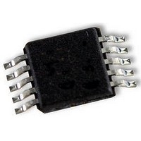
LMP7712MM National Semiconductor, LMP7712MM Datasheet - Page 15

LMP7712MM
Manufacturer Part Number
LMP7712MM
Description
OP AMP, 14MHZ, POWERWISE, MSOP10
Manufacturer
National Semiconductor
Datasheet
1.LMP7712MMNOPB.pdf
(20 pages)
Specifications of LMP7712MM
Op Amp Type
Low Noise
No. Of Amplifiers
2
Bandwidth
17MHz
Slew Rate
11.5V/µs
Supply Voltage Range
1.8V To 5.5V
Amplifier Case Style
MSOP
No. Of Pins
10
Operating Temperature Range
-40°C To
Lead Free Status / RoHS Status
Lead free / RoHS Compliant
Available stocks
Company
Part Number
Manufacturer
Quantity
Price
Company:
Part Number:
LMP7712MM/NOPB
Manufacturer:
National Semiconductor
Quantity:
1 886
This input capacitance will interact with other impedances
such as gain and feedback resistors, which are seen on the
inputs of the amplifier to form a pole. This pole will have little
or no effect on the output of the amplifier at low frequencies
and under DC conditions, but will play a bigger role as the
frequency increases. At higher frequencies, the presence of
this pole will decrease phase margin and also causes gain
peaking. In order to compensate for the input capacitance,
care must be taken in choosing feedback resistors. In addition
to being selective in picking values for the feedback resistor,
a capacitor can be added to the feedback path to increase
stability.
The DC gain of the circuit shown in Figure 3 is simply −R
R
For the time being, ignore C
Figure 3 can be calculated as follows:
This equation is rearranged to find the location of the two
poles:
1
.
FIGURE 3. Compensating for Input Capacitance
FIGURE 2. Input Common Mode Capacitance
F
. The AC gain of the circuit in
20150364
20150375
(1)
2
/
15
As shown in Equation 2, as the values of R
creased, the magnitude of the poles are reduced, which in
turn decreases the bandwidth of the amplifier. Figure 4 shows
the frequency response with different value resistors for R
and R
back resistors.
As mentioned before, adding a capacitor to the feedback path
will decrease the peaking. This is because C
another pole in the system and will prevent pairs of poles, or
complex conjugates from forming. It is the presence of pairs
of poles that cause the peaking of gain. Figure 5 shows the
frequency response of the schematic presented in Figure 3
with different values of C
ue capacitor significantly reduces or eliminates the peaking.
TRANSIMPEDANCE AMPLIFIER
In many applications, the signal of interest is a very small
amount of current that needs to be detected. Current that is
transmitted through a photodiode is a good example. Barcode
scanners, light meters, fiber optic receivers, and industrial
sensors are some typical applications utilizing photodiodes
FIGURE 4. Closed Loop Frequency Response
FIGURE 5. Closed Loop Frequency Response
2
. Whenever possible, it is best to chose smaller feed-
F
. As can be seen, using a small val-
1
and R
F
20150360
20150359
will form yet
www.national.com
2
are in-
(2)
1


