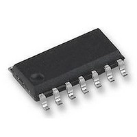
LF298M National Semiconductor, LF298M Datasheet - Page 6

LF298M
Manufacturer Part Number
LF298M
Description
AMP SAMPLE AND HOLD, SOIC14, 298
Manufacturer
National Semiconductor
Datasheet
1.LF298M.pdf
(13 pages)
Specifications of LF298M
No. Of Amplifiers
1
Acquisition Time
4µs
Input Offset Voltage
3mV
Supply Voltage Range
± 5V To ± 18V
Amplifier Case Style
SOIC
No. Of Pins
14
Operating Temperature Range
-25°C To +85°C
Svhc
No
Lead Free Status / RoHS Status
Lead free / RoHS Compliant
Available stocks
Company
Part Number
Manufacturer
Quantity
Price
Company:
Part Number:
LF298MX/NOPB
Manufacturer:
TI
Quantity:
6 552
www.national.com
Logic Input Configurations
Threshold = 0.6 (V
Threshold
Application Hints
Hold Capacitor
Hold step, acquisition time, and droop rate are the major
trade-offs in the selection of a hold capacitor value. Size and
cost may also become important for larger values. Use of the
curves included with this data sheet should be helpful in se-
lecting a reasonable value of capacitance. Keep in mind that
for fast repetition rates or tracking fast signals, the capacitor
drive currents may cause a significant temperature rise in
the LF198.
A significant source of error in an accurate sample and hold
circuit is dielectric absorption in the hold capacitor. A mylar
cap, for instance, may “sag back” up to 0.2% after a quick
change in voltage. A long sample time is required before the
circuit can be put back into the hold mode with this type of
capacitor. Dielectrics with very low hysteresis are polysty-
rene, polypropylene, and Teflon. Other types such as mica
and polycarbonate are not nearly as good. The advantage of
polypropylene over polystyrene is that it extends the maxi-
mum ambient temperature from 85˚C to 100˚C. Most ce-
ramic capacitors are unusable with
ramic “NPO” or “COG” capacitors are now available for
125˚C operation and also have low dielectric absorption. For
more exact data, see the curve Dielectric Absorption Error.
The hysteresis numbers on the curve are final values, taken
after full relaxation. The hysteresis error can be significantly
+4V
+
) + 1.4V
>
1% hysteresis. Ce-
DS005692-35
DS005692-37
(Continued)
7V
V
LOGIC
Op Amp Drive
CMOS
(Hi State)
Threshold = 0.6 (V
Threshold = −4V
6
reduced if the output of the LF198 is digitized quickly after
the hold mode is initiated. The hysteresis relaxation time
constant in polypropylene, for instance, is 10 — 50 ms. If
A-to-D conversion can be made within 1 ms, hysteresis error
will be reduced by a factor of ten.
DC and AC Zeroing
DC zeroing is accomplished by connecting the offset adjust
pin to the wiper of a 1 k
tied to V
The resistor should be selected to give 0.6 mA through the
1k potentiometer.
AC zeroing (hold step zeroing) can be obtained by adding an
inverter with the adjustment pot tied input to output. A 10 pF
capacitor from the wiper to the hold capacitor will give
hold step adjustment with a 0.01 µF hold capacitor and 5V
logic supply. For larger logic swings, a smaller capacitor
(
Logic Rise Time
For proper operation, logic signals into the LF198 must have
a minimum dV/dt of 1.0 V/µs. Slower signals will cause ex-
cessive hold step. If a R/C network is used in front of the
<
10 pF) may be used.
15V
+
and the other end tied through a resistor to ground.
+
) − 1.4V
potentiometer which has one end
DS005692-38
DS005692-36
±
4 mV


