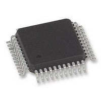
AS2525B austriamicrosystems, AS2525B Datasheet - Page 3

AS2525B
Manufacturer Part Number
AS2525B
Description
IC, SINGLE CHIP HANDS FREE PHONE, TQFP44
Manufacturer
austriamicrosystems
Datasheet
1.AS2525B.pdf
(27 pages)
Specifications of AS2525B
Audio Control Type
Volume
Output Power
500mW
Control Interface
Serial
Control / Process Application
Volume Control For Earpiece & Loudspeaker
Supply Voltage Range
3V To 5V
Lead Free Status / RoHS Status
Lead free / RoHS Compliant
Available stocks
Company
Part Number
Manufacturer
Quantity
Price
Datasheet AS2525
Revision 2.1
Pin #
19
20
21
22
23
24
25
26
27
28
29
30
31
32
33
34
35
36
37
38
39
40
41
42
Symbol
DM/HM
RECV
RECI
A
CBN
OSC
V
LO1
LO2
LED
CLK
V
V
FCI
RO
CM
R1
R2
R3
C1
C2
C3
C4
DI
GND
SSA
DD
PP
Supply
Supply
Supply
Supply
Type
DI/O
DI/O
AO
DO
AO
DO
DO
DI
DI
DI
AI
AI
AI
REC
Analogue input for the handsfree receive path. Should be connected to RO via a coupling
capacitor.
REC
Analogue input for receive voice switching path.
R
Output for driving a dynamic earpiece with an impedance from 150
V
Positive Power Supply.
A
Special ground for the internal amplifiers.
Analogue input pin for connecting a capacitor for background noise monitoring.
C
This is an output for controlling the external switching converter. During ringing it converts
the ring signal into a 4V supply voltage.
Loudspeaker Power Supply
High power supply for the output driver stage.
L
Output pins for a 32
Power supply pin for LO1-LO2 output amplifier.
D
Digital input for choosing between LD and MF dialing or choosing handset and headset
mode. See “Table 3: Parameter settings” for further details. This pin is scanned after manual
off-hook only.
F
This is a Schmitt-trigger input for ring frequency discrimination. Disabled during off-hook.
LED
Digital output for connecting 2 mA LED to indicate handsfree mode.
Osc
Input for ceramic resonator 3.58 MHz.
Keyboard
(see Figure 1: Keyboard Layout).
Keyboard
(see Figure 1: Keyboard Layout).
Cl
Clock output for 3-wire bus.
If signal is not activated, a pull down resistor (100 k ) is inserted.
D
Data input of 3-wire bus.
If signal is not activated, a pull down resistor (100 k ) is inserted.
oudspeaker
requency
oltage
nalogue
eceive
onverter
ial
ata
oc
M
illator Input
k
eive
eive
I
Output
nput
ode/
D
O
R
C
G
I
V
rain
M
utput to
nput
C
H
ows
olumns
oice Switching Input
rou
ake Output
omparator
O
eadset
D
nd
utputs
rain
H
M
andset
1/2
ode Switch Input
( 25 to 50
I
nput
) loudspeaker.
Description
austriamicrosystems
to 300
.
Page 3 of 27


