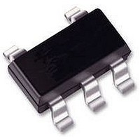
CAT4201TD-GT3 CATALYST SEMICONDUCTOR, CAT4201TD-GT3 Datasheet - Page 2

CAT4201TD-GT3
Manufacturer Part Number
CAT4201TD-GT3
Description
IC, LED DRIVER, BUCK, TSOT-23-5
Manufacturer
CATALYST SEMICONDUCTOR
Datasheet
1.CAT4201TD-GT3.pdf
(13 pages)
Specifications of CAT4201TD-GT3
Led Driver Application
Automotive Lighting
No. Of Outputs
1
Output Current
350mA
Output Voltage
32V
Input Voltage
6.5V To 36V
Dimming Control Type
PWM
Topology
Buck
Lead Free Status / RoHS Status
Lead free / RoHS Compliant
Available stocks
Company
Part Number
Manufacturer
Quantity
Price
Stresses exceeding Maximum Ratings may damage the device. Maximum Ratings are stress ratings only. Functional operation above the
Recommended Operating Conditions is not implied. Extended exposure to stresses above the Recommended Operating Conditions may affect
device reliability.
1. The VBAT pin voltage should be at least 3 V greater than the total sum of the LED forward voltages in order to operate at nominal LED current.
2. During power−up, the slew rate of the input supply should be greater than 1 ms for every 5 V increase of VBAT.
Table 1. ABSOLUTE MAXIMUM RATINGS
Table 2. RECOMMENDED OPERATING CONDITIONS
Table 3. ELECTRICAL CHARACTERISTICS
(V
V
VBAT voltage (Notes 1, 2)
SW voltage
Ambient Temperature Range
LED Current
Switching Frequency
VBAT, SW, CTRL
RSET
Switch SW peak current
Storage Temperature Range
Junction Temperature Range
Lead Temperature
V
V
IN
CTRL−FULL
Symbol
CTRL−EN
CTRL−SD
T
I
R
= 13 V, ambient temperature of 25°C (over recommended operating conditions unless otherwise specified))
I
CTRL
V
T
HYST
I
LED
I
SD
SW
SD
h
Q
FB
Operating Supply Current on VBAT pin
Idle Mode Supply Current on VBAT pin
RSET Pin Voltage
Programmed LED Current
CTRL Voltage for 100% Brightness
CTRL Voltage to Enable LEDs
CTRL Voltage to Shutdown LEDs
CTRL pin input bias
Switch “On” Resistance
Thermal Shutdown
Thermal Hysteresis
Efficiency
Parameters
Parameters
Parameter
http://onsemi.com
CTRL = GND
2 LEDs with I
R1 = 33 kW
R1 = 10 kW
R1 = 8.25 kW
LED enable voltage threshold
LED disable voltage threshold
V
V
I
Typical Application Circuit
SW
CTRL
CTRL
= 300 mA
2
= 3 V
= 12 V
Conditions
LED
= 300 mA
6.5 to 36 (Note 1)
−65 to +160
−40 to +150
−40 to +125
−0.3 to +40
50 to 1000
−0.3 to +5
50 to 350
Ratings
Ratings
0 to 36
300
1
1.15
Min
270
0.4
Typ
100
300
350
200
150
0.4
1.2
2.6
0.9
0.9
0.9
90
40
20
86
Max
1.25
330
3.1
1.2
1.5
80
1
Units
Units
kHz
mA
_C
_C
_C
_C
V
V
A
V
V
Units
mA
mA
mA
mA
°C
°C
W
%
V
V
V
V


