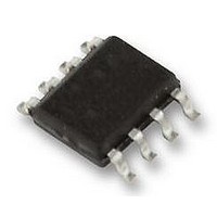
LM27222M National Semiconductor, LM27222M Datasheet - Page 7

LM27222M
Manufacturer Part Number
LM27222M
Description
MOSFET DRIVER/PWM CONTROL, 27222
Manufacturer
National Semiconductor
Datasheet
1.LM27222M.pdf
(11 pages)
Specifications of LM27222M
Device Type
MOSFET
Module Configuration
High Side / Low Side
Peak Output Current
4.5A
Output Resistance
10kohm
Supply Voltage Range
4V To 7V
Driver Case Style
SOIC
No. Of Pins
8
Operating
RoHS Compliant
Available stocks
Company
Part Number
Manufacturer
Quantity
Price
Part Number:
LM27222MX
Manufacturer:
NS/国半
Quantity:
20 000
Application Information
MINIMUM PULSE WIDTH
As the input pulse width to the IN pin is decreased, the pulse
width of the high-side gate drive (HG-SW) also decreases.
However, for input pulse widths 60ns and smaller, the
HG-SW remains constant at 30ns. Thus the minimum pulse
width of the driver output is 30ns. Figure 5 shows an input
pulse at the IN pin 20ns wide, and the output of the driver, as
measured between the nodes HG and SW is a 30ns wide
pulse. Figure 6 shows the variation of the SW node pulse
width vs IN pulse width. At the IN pin, if a falling edge is
followed by a rising edge within 5ns, the HG may ignore the
rising edge and remain low until the IN pin toggles again. If a
rising edge is followed by a falling edge within 5ns, the pulse
may be completely ignored.
ADAPTIVE SHOOT-THROUGH PROTECTION
The LM27222 prevents shoot-through power loss by ensur-
ing that both the high- and low-side MOSFETs are not con-
ducting at the same time. When the IN signal rises, LG is first
pulled down. The adaptive shoot-through protection circuit
waits for LG to reach 0.9V before turning on HG. Similarly,
FIGURE 5. Min On Time
FIGURE 6.
20117905
20117906
7
when IN goes low, HG is pulled down first, and the circuit
turns LG on only after the voltage difference between the
high-side gate and the switch node, ie HG-SW, has fallen to
0.9V. The dead-time between the high and low-side pulses is
kept as small as possible to minimize conduction through the
body diode of the low-side MOSFET(s).
POWER DISSIPATION
The power dissipated in the driver IC when switching syn-
chronously can be calculated as follows:
where f
V
Q
high-side MOSFET(s)
Q
low-side MOSFET(s)
R
high-side MOSFET(s)
R
low-side MOSFET(S)
R
R
R
R
PC BOARD LAYOUT GUIDELINES
1. Place the driver as close to the MOSFETs as possible
2. HG, SW, LG, GND: Run short, thick traces between the
3. Driver V
4. The high-current loop between the high-side and low-
5. There should be enough copper area near the MOS-
TYPICAL APPLICATION CIRCUIT DESCRIPITON
The Typical Application Circuit shown on the following page
shows the LM27222 being used with National’s LM27212
2-Phase Hysteretic Current mode controller. Although this
circuit is capable of operating from 5V to 28V, the compo-
nents are optimized for a input voltage range of 9V to 28V.
The high-side FET is selected for low gate charge to reduce
switching losses. For low duty cycles, the average current is
relatively small and thus we trade off higher conduction
losses for lower switching losses. The low side FET is se-
lected solely on R
input voltage range were 4V to 6V, the MOSFET selection
should be changed. First, much lower voltage FETs can be
CC
G_H
G_L
G_H
G_L
H_pu
H_pd
L_pu
L_pd
driver and the MOSFETs. To minimize parasitics, the
traces for HG and SW should run parallel and close to
each other. The same is true for LG and GND
V
side MOSFETs and the input capacitors should be as
small as possible
FETs and the inductor for heat dissipation. Vias may
also be added to carry the heat to other layers
= voltage at the V
CC
= total gate charge of the (parallel combination of the)
= gate resistance of the (parallel combination of the)
= total gate charge of the (parallel combination of the)
= gate resistance of the (parallel combination of the)
= pull-up R
= pull-down R
= pull-up R
= pull-down R
SW
and GND pins
= switching frequency
CC
: Place the coupling capacitor close to the
DS_ON
DS_ON
DS_ON
DS_ON
DS_ON
CC
to minimize conduction losses. If the
of the low-side driver
of the high-side driver
pin,
of the low-side driver
of the high-side driver
www.national.com


