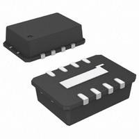
ADL5350ACPZ-R7 Analog Devices Inc, ADL5350ACPZ-R7 Datasheet - Page 21

ADL5350ACPZ-R7
Manufacturer Part Number
ADL5350ACPZ-R7
Description
IC, HIGH LINEARITY Y-MIXER 4GHZ, LFCSP-8
Manufacturer
Analog Devices Inc
Series
ADL5350r
Datasheet
1.ADL5350ACPZ-R7.pdf
(24 pages)
Specifications of ADL5350ACPZ-R7
Frequency Range
750MHz To 2.05GHz
Supply Voltage Range
2.7V To 3.5V
Rf Ic Case Style
LFCSP
No. Of Pins
8
Operating Temperature Range
-40°C To +85°C
Rf Type
General Purpose
Frequency
750MHz ~ 4GHz
Number Of Mixers
1
Noise Figure
6.5dB
Current - Supply
16.5mA
Voltage - Supply
2.7 V ~ 3.5 V
Package / Case
8-VFDFN, CSP Exposed Pad
Operating Supply Voltage
3V
Operating Temperature (min)
-40C
Operating Temperature (max)
85C
Operating Temperature Classification
Industrial
Rohs Compliant
Yes
Lead Free Status / RoHS Status
Lead free / RoHS Compliant
Gain
-
Secondary Attributes
-
Lead Free Status / Rohs Status
Compliant
Other names
ADL5350ACPZ-R7TR
Available stocks
Company
Part Number
Manufacturer
Quantity
Price
Company:
Part Number:
ADL5350ACPZ-R7
Manufacturer:
ADI
Quantity:
2
EVALUATION BOARD
An evaluation board is available for the ADL5350. The evaluation board has two halves: a low band board designated as Board A
and a high band board designated as Board B. The schematic for the evaluation board is shown in Figure 65.
Table 9. Evaluation Board Configuration Options
Component
C4-A, C4-B,
C5-A, C5-B
L1-A, L1-B,
C1-A, C1-B
L2-A, L2-B,
C2-A, C2-B,
C6-A, C6-B
L3-A, L3-B,
C3-A, C3-B
L4-A, L4-B
Function
Supply Decoupling. C4-A and C4-B provide local bypassing of the supply.
C5-A and C5-B are used to filter the ripple of a noisy supply line. These are not
always necessary.
RF Input Network. Designed to provide series resonance at the intended
RF frequency.
IF Output Network. Designed to provide parallel resonance at the geometric mean
of the RF and LO frequencies.
LO Input Network. Designed to block dc and optimize LO voltage swing at LOIN.
LO Buffer Amplifier Choke. Provides bias and ac loading impedance to LO buffer
amplifier.
RF-A
IF-A
L1-A
L2-A
C1-A
RF/IF
RF/IF
8
1
C6-A
C2-A
GND2
NC
ADL5350
7
2
LO-A
U1-A
VPOS-A
VPOS
LOIN
6
3
C5-A
C4-A
L3-A
L4-A
C3-A
Figure 65. Evaluation Board
GND1
Rev. 0 | Page 21 of 24
NC
5
4
RF-B
IF-B
L1-B
L2-B
C1-B
RF/IF
RF/IF
8
1
C6-B
C2-B
GND2
NC
ADL5350
7
2
LO-B
U1-B
VPOS-B
VPOS
LOIN
6
3
C5-B
C4-B
L3-B
L4-B
C3-B
Default Conditions
C4-A = C4-B = 100 pF,
C5-A = C5-B = 4.7 μF
L1-A = 6.8 nH (0603CS from Coilcraft),
L1-B = 1.7 nH (0302CS from Coilcraft),
C1-A = 4.7 pF, C1-B = 1.5 pF
L2-A = 4.7 nH (0603CS from Coilcraft),
L2-B = 1.7 nH (0302CS from Coilcraft),
C2-A = 5.6 pF, C2-B = 1.2 pF,
C6-A = C6-B = 1 nF
L3-A = 8.2 nH (0603CS from Coilcraft),
L3-B = 3.5 nH (0302CS from Coilcraft),
C3-A = C3-B = 100 pF
L4-A = 24 nH (0603CS from Coilcraft),
L4-B = 3.8 nH (0302CS from Coilcraft)
GND1
NC
5
4
ADL5350


