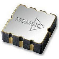
MXR2312ML MEMSIC, MXR2312ML Datasheet - Page 5

MXR2312ML
Manufacturer Part Number
MXR2312ML
Description
ACCELEROMETER, 2 AXIS, ±2G, LCC8
Manufacturer
MEMSIC
Datasheet
1.MXR2312ML.pdf
(6 pages)
Specifications of MXR2312ML
No. Of Axes
2
Sensor Case Style
LCC
No. Of Pins
8
Supply Voltage Range
3V To 5.25V
Operating Temperature Range
-40°C To +105°C
Operating Temperature Max
105°C
Operating
RoHS Compliant
Acceleration Range
±2g
Sensitivity Per Axis
312mV / G
Rohs Compliant
Yes
The peak-to-peak noise is approximately equal to 6.6 times
the rms value (for an average uncertainty of 0.1%).
EXTERNAL FILTERS
AC Coupling: For applications where only dynamic
accelerations (vibration) are to be measured, it is
recommended to ac couple the accelerometer output as
shown in Figure 3. The advantage of ac coupling is that
variations from part to part of zero g offset and zero g
offset versus temperature can be eliminated. Figure 3 is a
HPF (high pass filter) with a –3dB breakpoint given by the
equation:
desirable to have the HPF –3dB point at a very low
frequency in order to detect very low frequency
accelerations. Sometimes the implementation of this HPF
may result in unreasonably large capacitors, and the
designer must turn to digital implementations of HPFs
where very low frequency –3dB breakpoints can be
achieved.
Low Pass Filter: An external low pass filter is useful in
low frequency applications such as tilt or inclination. The
low pass filter limits the noise floor and improves the
resolution of the accelerometer. When designing with
MEMSIC ratiometric output accelerometers (MXRxxxx
series), it is highly recommended that an external, 20 Hz
low pass filter be used to eliminate internally generated
periodic noise that is coupled to the output of the
accelerometer. The low pass filter shown in Figure 4 has a
–3dB breakpoint given by the equation:
the 200 Hz ratiometric output device filter, C=0.2µF and
R=39kΩ, ±5%, 1/8W.
MEMSIC MXR2312G/M Rev.G
A
A
OUTX
OUTY
f
=
1
2
Figure 3: High Pass Filter
π
RC
C
C
. In many applications it may be
R
R
f
Filtered
Filtered
Output
Output
=
A
A
OUTX
1
OUTY
2
π
RC
. For
Page 5 of 6
POWER SUPPLY NOISE REJECTION
Two capacitors and a resistor are recommended for best
rejection of power supply noise (reference Figure 5 below).
The capacitors should be located as close as possible to the
device supply pins (V
should be as short as possible, and surface mount capacitors
are preferred. For typical applications, capacitors C1 and
C2 can be ceramic 0.1 µF, and the resistor R can be 10 Ω.
Figure 5: Power Supply Noise Rejection
PCB LAYOUT AND FABRICATION SUGGESTIONS
1. The Sck pin should be grounded to minimize noise.
2. Liberal use of ceramic bypass capacitors is
3. Robust low inductance ground wiring should be used.
4. Care should be taken to ensure there is “thermal
5. A metal ground plane should be added directly beneath
6. Vias can be added symmetrically around the ground
C1
V SUPPLY
recommended.
symmetry” on the PCB immediately surrounding the
MEMSIC device and that there is no significant heat
source nearby.
the MEMSIC device. The size of the plane should be
similar to the MEMSIC device’s footprint and be as
thick as possible.
plane. Vias increase thermal isolation of the device
from the rest of the PCB.
A
A
OUTX
OUTY
VDA
MEMSIC
Accelerometer
Figure 4: Low Pass Filter
R
R
R
DA
VDD
, V
DD
C2
). The capacitor lead length
C
C
Filtered
Filtered
Output
Output
A
A
OUTX
OUTY
2/26/2007


